Table of Contents
Advertisement
Quick Links
Advertisement
Table of Contents

Related Manuals for SamanTree Medical Histolog Scanner

Summary of Contents for SamanTree Medical Histolog Scanner
- Page 1 Instructions For Use 1223 version 1.5 (2019-06-21)
- Page 2 SamanTree Medical. Histolog is a registered trademark of SamanTree Medical. The Histolog® Scanner is protected by U.S. Patents 10,094,784 and 10,088,427.
-
Page 3: Table Of Contents
1. Table of Contents 1. Table of Contents 2. Explanation of symbols 3. Introduction 3.1. Manufacturer 3.2. System Description 3.2.1. Summary 3.2.2. Accessories and other parts 3.2.3. Operating Principle 3.3. Intended use 3.4. Indication for use 3.5. Contraindications 3.6. Intended patient population 3.7. - Page 4 6.1.1. Installing in use location 6.1.2. Connecting to mains power outlet 6.1.3. Switching ON 6.1.4. Mounting Histolog® Dish 6.2. After Use 6.2.1. Switching OFF 6.2.2. Prepare for storage 6.3. Tissue Specimen Imaging 6.3.1. Tissue specimen staining procedure 6.3.2. Tissue specimen positioning 6.4.
- Page 5 6.5.2.2. Generate an Acquire image 6.5.3. Open an image from the Gallery in Image Examiner screen 6.5.4. Navigate within an image in Image Examiner screen 6.5.5. Show/Hide Orientation Mark on an image 6.5.6. Change image Color Mode in Image Examiner screen 6.5.7.
- Page 6 10.1. Histolog® Dish 10.2. Histolog® Scanner 10.3. Histolog® Dip 11. Troubleshooting 12. Product Catalog Codes 13. Device specifications/Technical Information 13.1. Technical Specifications 13.1.1. Histolog® Scanner 13.1.2. Histolog® Dish 13.2. Electromagnetic Compatibility 13.3. Electromagnetic immunity 1223 version 1.5 (2019-06-21) Page 6 | 69...
-
Page 7: Explanation Of Symbols
2. Explanation of symbols Batch Code Catalog Number Serial Number In vitro diagnostic medical device Do not reuse Use-by (expiry) date Non-sterile Quantity in package Manufacturer Consult Instructions for Use Temperature limit Atmospheric Pressure Limitation Humidity Limitation Laser Class 1 Standby or power indicator 1223 version 1.5 (2019-06-21) - Page 8 This symbol indicates to follow the local regulations for separate collection of Electrical and Electronic Equipment. The device complies with European Directive 98/79/EC Manufacturing date Orientation mark Non-ionizing radiation Fragile; handle with care This way up Keep dry ● When followed by “ WARNING ” this symbol means “Warning! Failure to observe could result in injury or death.”...
-
Page 9: Introduction
Failure to properly follow Warnings, Cautions and Instructions could result in death or serious injury. 3.1. Manufacturer SamanTree Medical SA Rue de Genève 88bis 1004 Lausanne Switzerland Tel: +41 21 625 09 40 info@samantree.com... -
Page 10: Accessories And Other Parts
3.2.2. Accessories and other parts The Histolog® Dish is a single-use accessory receptacle on which tissue specimens are placed for imaging with Histolog® Scanner. The Histolog® Dip is a fluorescent histological stain for imaging tissue specimen with the Histolog® Scanner. It is an accessory product for the Histolog®... -
Page 11: Contraindications
3.5. Contraindications The Histolog® Scanner is not indicated in the following cases: ● For in-vivo tissue examination ● To replace standard postoperative assessment 3.6. Intended patient population The Histolog® Scanner and its accessory products shall not be used directly on patients. They shall be used for examination of surgical tissue after surgical excisions of tissue specimen. -
Page 12: Warnings & Precautions
The components located in the inner cavity of the device are not intended to be manipulated by the user. The interior of the Histolog® Scanner may be serviced only by SamanTree Medical authorized technical personnel. 4.2. Warnings WARNING ●... -
Page 13: Cautions
4.3. Cautions CAUTION ● Do not operate the Histolog® Scanner in case of damage to the imaging window [C1]. ● Do not re-use a Histolog® Dish. A new Histolog® Dish [C2] shall be used for every new surgical procedure. ● Do not use expired consumables with the Histolog® Scanner. ●... -
Page 14: Device Overview
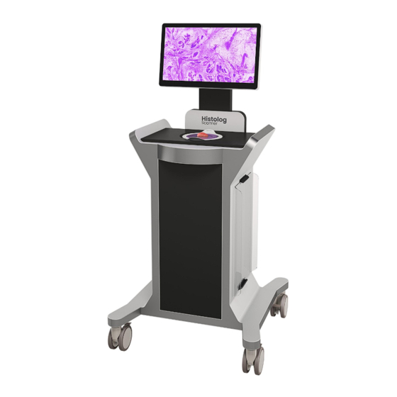
5. Device Overview 5.1. Overview 1223 version 1.5 (2019-06-21) Page 14 | 69... - Page 15 The Histolog® Scanner consists of the following components: A. Display Monitor B. Handles C. Specimen Imaging Area with a Histolog® Dish D. Cable Winder E. Histolog® Scanner Application with its graphical user interface F. ON/OFF Power Switch G. USB port H.
-
Page 16: Component Description
SamanTree Medical authorized technical personnel only. The Histolog® Scanner Application [E] is the software application supplied by SamanTree Medical SA for the operation of the Histolog® Scanner. It has a graphical user interface (GUI) through which the user can interact with the device. - Page 17 The Specimen Imaging Area [C] contains the following components: Imaging window Histolog® Dish (to be placed before use) Orientation Mark Tissue specimen is placed over the Imaging window [C1] covered by the Histolog® Dish, for imaging. Laser radiation in the visible wavelength range is emitted from the imaging window [C1] of the specimen imaging area [C] during imaging.
-
Page 18: The Histolog® Dish
The Histolog® Dish [C2] is the receptacle accessory that is placed over the Imaging area of the Histolog® Scanner and on which the tissue specimen is placed for imaging. It is composed of: 1. Two handles [C2.1] for manipulation; 2. An Optical Interface [C2.2] through which specimen is imaged. 1223 version 1.5 (2019-06-21) Page 18 | 69... -
Page 19: Use Of The Histolog® Scanner
6. Use of the Histolog® Scanner The device is to be delivered, commissioned, and decommissioned by SamanTree Medical authorized technical personnel only. 6.1. Before Use 6.1.1. Installing in use location 1. Move the Histolog® Scanner to desired location with level ground. -
Page 20: Mounting Histolog® Dish
6.1.4. Mounting Histolog® Dish 1. Remove the Lid [I], and store it in its Lid Storage Supports [M]. 2. Unpack a Histolog® Dish and mount it over the Specimen Imaging Area [C]. CAUTION ● Do not re-use a Histolog® Dish. A new Histolog® Dish [C2] shall be used for every new surgical procedure. -
Page 21: After Use
6.2. After Use 6.2.1. Switching OFF 1. Quit Histolog® Scanner Application by tapping the Turn Off button (A14 - §6.4.1.3 ) on the touch screen. 2. Confirm the action by tapping on “Turn off” button to shutdown the device. Or tap on “Cancel” if you do not want to shutdown the Histolog®... -
Page 22: Prepare For Storage
6.2.2. Prepare for storage 1. Dispose of the Histolog® Dish according to local procedure for handling biomedical waste. 2. Clean the Histolog® Scanner according to section of this manual. 3. Place the Lid [I] back over the Specimen Imaging Area. 1223 version 1.5 (2019-06-21) Page 22 | 69... -
Page 23: Tissue Specimen Imaging
6.3. Tissue Specimen Imaging WARNING When handling potentially infectious tissue specimens, avoid skin contact by wearing gloves or other protective equipment. By this point during surgery, the specimen is already marked for orientation. NOTE Image quality is negatively impacted by histological inks and excess of blood. -
Page 24: Histolog® Scanner Application
6.4. Histolog® Scanner Application Through the Histolog® Scanner Application, User controls operation of the Histolog® Scanner and works with digital images generated using the device. The work with digital images is organized in Sessions, where a Session encompasses a set of images. This set of images is intended to relate to a single patient or surgery and can comprise up to five specimens per Session. -
Page 25: Gallery Screen: Sessions Browsing And Contextual Data Controls [B]
A1. Preview button launches a fast Preview imaging of a specimen. A2. Cancel button interrupts an ongoing Preview imaging process. A3. Acquire button launches a high resolution Acquire imaging of a specimen. A4. Cancel button interrupts an ongoing Acquire imaging process. A5. - Page 26 B2. Current Session . The upper line session in Recent Sessions list is the current session, to which newly captured Histolog® Scanner Preview and Acquire images will belong. B3. Previous Sessions . Scroll the list of Recent Sessions to locate any of the previous sessions that was performed on the device (and was not deleted).
-
Page 27: Service Functionalities
6.4.2.2. Service functionalities B7. Date and Clock. At the bottom left corner of the screen are shown current date and time. B8. Histolog® Scanner logo. Tapping on the Histolog® Scanner logo activates Histolog® Scanner service dialog window. This dialog window is not used for regular Histolog®... -
Page 28: Sessions Contextual Data
6.4.2.3. Sessions contextual data The next part of Gallery screen [B] allows to browse through sessions and images, and manage their related contextual data. A session contextual data includes: B10. Date and time of when the session was created (cannot be changed). - Page 29 B14. Session Description serves to specify a textual description of the Session . Session Description is empty when session starts, and can be edited, if and when needed. To edit using a virtual keyboard, simply tap the button. B13.1. Specimen Location map is a schematic representation of the patient “Left”...
- Page 30 B13.3. Move Location button. If the button is active (colored in blue), a user can move existing location tags on the map, dragging them with a finger. If the button is not active (not colored in blue), it can be activated by tapping.
- Page 31 B13.4. Location selection. An existing location must be selected before deleting it. Selection tools are comprised of Select All button and check marks on location tags. Tapping on an individual location tag will place a check mark on it and thus select it for a possible deletion. Tapping on Select All button will select all location tags for a potential deletion.
-
Page 32: Gallery Content: Single Session View
6.4.2.4. Gallery content: Single Session view B15. Single Session view. This Gallery view is activated when a user taps on a particular session. This view features: B15.1. Image thumbnail and information allow to rapidly identify an image of interest. From left to right, the following information is displayed below an image thumbnail: image creation date and time (not editable), image type (Preview, Acquire or View, not editable), imaged specimen location color tags (editable), as well as optional image description on... - Page 33 B15.4. Export button. The button becomes active as soon as some of the session images are selected using selection tools (B15.2). Touching the button will display the choice available for the kinds of export, namely: ● Export image(s); ● Export image(s) and metadata; ●...
- Page 34 B15.5. Specimen location color tags. These are the tags that represent specimen locations defined through the session’s Specimen Location map (B13) interface. Touching the tag area will display a graphical control allowing for a change of the image specimen location color tag.
-
Page 35: Gallery Content: All Sessions View
B15.6. Annotation icon. If an image contains one or several annotations that were introduced by users, then on Gallery screen the image thumbnail will be shown with the annotation icon in the lower right corner. B15.7. Specimen Surface Orientation icon. If users defined a Specimen Surface Orientation for an image (using the tool that will be presented on Image Examiner screen as C4), then on Gallery screen the image thumbnail will be shown with the Specimen Surface Orientation... -
Page 36: Image Examiner Screen
Tapping on the image icons will open the corresponding session in Single Session Gallery view (B15). Analogously to Single Session view, All Sessions view also features Selection tools (B15.2), Delete button (B15.3) and Export button (B15.4). These are the same tools that were already described earlier. 6.4.3. -
Page 37: Image Contextual Data Pane
6.4.3.1. Image contextual data pane Image contextual data pane includes: Image Timestamp Description. Image creation date and time cannot be changed, while Image Description, initially empty, can be edited. Edit Image Description, if needed, by tapping button enter description using virtual keyboard. -
Page 38: Image Area With Navigator
6.4.3.2. Image Area with Navigator Image Area with Navigator contains: C8. Image Area. This is the area where the image is displayed. In this area users can work with the image using Image toolbar and navigate through the image using regular touch screen gestures for image navigation. -
Page 39: Image Toolbar
6.4.3.3. Image toolbar The Image toolbar contains a set of tools that can be used to work with the displayed image: C10. Fit to Screen Height. Touching this button displays the image minimized to fit to screen height. This is the minimum zoom level: image may not be further zoomed out. - Page 40 Auto button ( C18.2 ) - for an automatic adjustment optimized for the current Image area displayed on the screen. Reset button ( C18.3 ) - to quickly return to the initial, non-adjusted display. C19. Annotations. A toolbar is activated by tapping C19 button.
- Page 41 C19.5. Delete Annotation. This button is used to delete a selected graphic annotation (Free Form, Line or Pinpoint). C19.6. Annotation Visibility. The button is used to show or hide the display of all annotations on the image. 1223 version 1.5 (2019-06-21) Page 41 | 69...
-
Page 42: Use Of Histolog® Scanner Application
6.5. Use of Histolog® Scanner Application 6.5.1. Enter Session contextual data The picture above shows the screen of Histolog® Scanner after the application startup. At startup, the application creates a new session and invites users to enter the session contextual data. This is an optional step. -
Page 43: Generate An Image Of A Tissue Specimen
6. Using the Specimen Location map graphical control add to the map a location indicating position where the specimen imaged during the current session is (or will be) located. NOTE Application allows for adding several (up to five) locations for the specimens imaged during the current session. -
Page 44: Generate A Preview Image
Acquire This mode allows to get a high resolution image. Generation of an Acquire image will take more time than with the Preview. 6.5.2.1. Generate a Preview image Click on Preview button (A1). Wait for the Progress indicator (A5) to indicate a full completeness state. -
Page 45: Show/Hide Orientation Mark On An Image
Navigator control (C9) located in the top right corner of the image allows to identify which portion of the full image is currently displayed in the Image Area. 6.5.5. Show/Hide Orientation Mark on an image When a Preview or an Acquire image is opened in Image Examiner: Tap on Orientation Mark tool button (C15) to show the mark in the current image view, next to the Navigator control. -
Page 46: Specify Specimen Surface Orientation For An Image
2. Using on-screen virtual keyboard enter description for the image. 3. Tap Image Timestamp and Description button once again to return to the image display. 6.5.10. Specify Specimen Surface Orientation for an image For a Preview or an Acquire image opened in Image Examiner screen: 1. -
Page 47: Work With Line Annotations
Tap on the line of free form annotation that you added on step 3 in order to select the annotation. Delete the selected annotation using Delete Annotation button (C19.5) Tap on Annotation toolbar button (C19) to deactivate the corresponding control. 6.5.11.2. -
Page 48: Work With Pinpoint Annotations
6.5.11.3. Work with Pinpoint Annotations For a Preview or an Acquire image opened in Image Examiner screen: Annotation toolbar button (C19) activate corresponding control. Tap on Pinpoint Annotation button (C19.3) to activate the corresponding tool. Introduce a pinpoint annotation on the image by touching the image area. - Page 49 2. Select the Gallery content that you want to export using selection tools (B15.2). 3. Tap on Export button (B15.4) to display export options. a. Tap on the option “Export Image(s)” to copy the selected content of the Gallery to your USB storage device as image files that can be viewed using a standard third-party viewer.
-
Page 50: Delete Gallery Content
6.5.13. Delete Gallery content Select the Gallery content you want to delete using selection tools (B15.2). Tap the Delete button (B15.3) to delete the selected content. The deleted selection will be moved to “Deleted Items” collection. After deletion of the selected content, a temporary confirmation message will appear in the lower right corner of the screen. - Page 51 3. Tap the Delete button to permanently delete the selected content. NOTE Permanent deletion cannot be undone. Deleted content will be lost for good. If you are sure that you really want to permanently delete the selected content, then confirm your action by clicking on “Delete” on the confirmation dialog.
-
Page 52: Storage
7. Storage After use of this device, follow the instructions of section of this manual. The device can then be moved to the storage area. Apply the brakes to prevent unintended motion during storage. See section 13.1 for specified environmental storage conditions. ... -
Page 53: Moving
8. Moving Before moving the Histolog® Scanner, please ensure that: 1. The power cord is disconnected from mains outlet and secured on the cable winder 2. The brakes of the caster wheels are released Move the device no faster than walking speed. WARNING Handles are not provided for lifting the device, but exclusively have a function for pushing/pulling. -
Page 54: Maintenance & Cleaning
The components located in the inner cavity of the device are not intended to be manipulated by the user. The interior of the Histolog® Scanner may be serviced only by SamanTree Medical authorized technical personnel. 9.1.1. Update of Histolog® Scanner software application Update of Histolog®... - Page 55 Figure Fuse compartment located above the mains appliance inlet. To replace fuses: 1. With Scanner switched off, disconnect power cord from appliance inlet 2. Using a flat screwdriver or a coin, open the fuse drawer (see Figure above) on the back of the device. 3.
-
Page 56: Cleaning Procedures
9.2. Cleaning procedures 9.2.1. Cleaning the Histolog® Scanner CAUTION Cleaning when device is turned ON and connected to the main power source may be hazardous to the operator and/or destructive to the device. Device may be cleaned with conventional alcohol-based disinfecting agents for medical devices. -
Page 57: Disposal
10. Disposal 10.1. Histolog® Dish Dispose of the Histolog® Dish according to local procedure for handling biomedical waste. 10.2. Histolog® Scanner Follow the local regulations for separate collection of Electrical and Electronic Equipment. 10.3. Histolog® Dip Dispose of the Histolog® Dip in accordance with the information contained in its Instructions For Use. -
Page 58: Troubleshooting
11. Troubleshooting Issue Action to take Device does not power up Check that power cord is connected to mains power outlet and that Histolog® Scanner is switched ON (power switch is pressed and lighted ON). If it still doesn’t power up, verify that the fuses haven’t blown. - Page 59 If the problem cannot be corrected stop using the device. Shut down and prepare for storage as per section . Contact SamanTree Medical for technical support (contact information may be found in section 1223 version 1.5 (2019-06-21)
-
Page 60: Product Catalog Codes
12. Product Catalog Codes To purchase replacement parts from SamanTree Medical or from an authorized SamanTree Medical distributor, please use the following product catalog numbers. Products Product Catalog Code Description (REF) Histolog® Scanner 004 (HL.DH220) Histolog® Dish Histolog® Dip Replacement Parts... -
Page 61: Device Specifications/Technical Information
13. Device specifications/Technical Information 13.1. Technical Specifications 13.1.1. Histolog® Scanner HISTOLOG® SCANNER Dimensions (W x D x H) 0.76 m x 0.76 m x 1.56 m Weight 95 kg Electrical Power Input 100–240 VAC, 50/60 Hz Maximum Rated Power 305 W Power Cord Length RoHS Compliant Yes (Directive 2011/65/EU) - Page 62 Display Active screen size (diagonal) 547 mm (21.5”) Active screen size (W x H) 476.64 mm x 268.11 mm (18.77” x10.56”) Resolution 2 MP (1920 x 1080) Viewing angle (H, V) 178° Contrast ratio 3000:1 typical Fluorescence Settings Laser wavelength 488 ±4 nm Emission filter Longpass, cut-on at 500±3 nm...
-
Page 63: Histolog® Dish
13.1.2. Histolog® Dish HISTOLOG® DISH Outer Dimensions (L x W x H) 239 mm x 200 mm x 26 mm Inner Dimension (Ø) 159 mm Weight 54 g 1223 version 1.5 (2019-06-21) Page 63 | 69... -
Page 64: Electromagnetic Compatibility
13.2. Electromagnetic Compatibility The Histolog® Scanner complies with the emission and immunity requirements of IEC 61326-2-6:2012. Guidance and manufacturer’s declaration – Electromagnetic emissions The Histolog® Scanner is intended for use in the electromagnetic environment specified below. The customer or the user of the Histolog® Scanner should ensure that it is used in such an environment. -
Page 65: Electromagnetic Immunity
13.3. Electromagnetic immunity Guidance and manufacturer’s declaration – Electromagnetic immunity The Histolog® Scanner is intended for use in the electromagnetic environment specified below. The customer or the user of the Histolog® Scanner should ensure that it is used in such an environment. Immunity test IEC 61326-2-6 Compliance level... - Page 66 (>95% dip in UT) (100% dip in UT) the Histolog® for 5 s For 5 s Scanner be powered from an uninterruptible power supply. Power frequency 3 A/m Complies Power frequency (50/60 Hz) (does not contain magnetic fields magnetic field any components should IEC 61000-4-8...
- Page 67 Recommended separation distance d = 1.17 * √P d = 1.17 * √P 80 MHz to 800 d = 2.33 * √P 800 MHz to 2.5 where P is the maximum output power rating of the transmitter in watts (W) according to the transmitter manufacturer and d is the...
- Page 68 Field strengths from fixed transmitters, such as base stations for radio (cellular/cordless) telephones and land mobile radios, amateur radio, AM and FM radio broadcast and TV broadcast cannot be predicted theoretically with accuracy. To assess the electromagnetic environment due to fixed RF transmitters, an electromagnetic site survey should be considered.
- Page 69 Recommended separation distances between portable and mobile RF communications equipment and the Histolog® Scanner The Histolog® Scanner is intended for use in an electromagnetic environment in which radiated RF disturbances are controlled. The customer of the user of the Histolog® Scanner can help prevent electromagnetic interference by maintaining a minimum distance between portable and mobile RF communications equipment (transmitters) and the Histolog®...
Need help?
Do you have a question about the Histolog Scanner and is the answer not in the manual?
Questions and answers