Table of Contents
Advertisement
Quick Links
USB
TF
INPUT1
INPUT2
INPUT3
INPUT4
MIN
MAX
MIN
MAX
MIN
MAX
MIN
Please follow the instructions in this manual to obtain the optimum results from this unit.
We also recommend that you keep this manual handy for future reference.
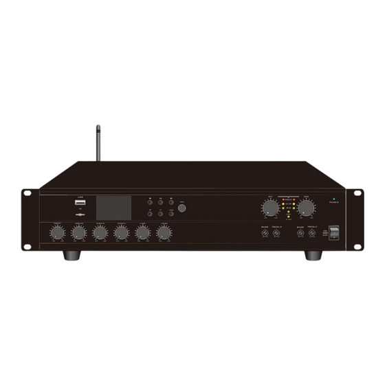
PUBLIC ADDRESS SYSTEM
CLASS D POWER AMPLIFIER
MENU
V
V+
MODE
LINE1
LINE2
MAX
MIN
MAX
MIN
MAX
SF-2240UC
CH1
CH2
PROT
POWER
CLIP
SIG
100V
MIN
MAX
MIN
MAX
4-16
Ω
dB
dB
dB
dB
-10
+10
-10
+10
-10
+10
-10
+10
Advertisement
Table of Contents

Related Manuals for Epcom PROAUDIO SF-2240UC


Summary of Contents for Epcom PROAUDIO SF-2240UC
- Page 1 PUBLIC ADDRESS SYSTEM SF-2240UC CLASS D POWER AMPLIFIER PROT MENU POWER CLIP MODE 100V 4-16 Ω INPUT1 INPUT2 INPUT3 INPUT4 LINE1 LINE2 Please follow the instructions in this manual to obtain the optimum results from this unit. We also recommend that you keep this manual handy for future reference.
-
Page 2: Table Of Contents
TABLE OF CONTENTS 1. SAFETY PRECAUTIONS ..................3 2. GENERAL DESCRIPTION ..................5 3. FEATURES .......................5 4. NOMENCLATURE AND FUNCTIONS 4.1 Front Panel ......................6 4.2 Rear Panel....................... 7 5. OPERATION ILLUSTRATION ................8 6. SCREEN OPERATION INSTRUCTIONS ............. 11 7. TROUBLESHOOTING ....................15 8. APPLICATIONS ..................... -
Page 3: Safety Precautions
1. SAFETY PRECAUTIONS Be sure to read the instructions in this section carefully before use. Make sure to observe the instructions in this manual as the conventions of safety symbols and messages regarded as very important precautions are included. We also recommend you keep this instruction manual handy for future reference. Safety Symbol and Message Conventions Safety symbols and messages described below are used in this manual to prevent bodily injury and property damage which could result from mishandling. - Page 4 SAFETY PRECAUTIONS When the Unit is in Use When Installing the Unit Do not place heavy objects on the unit as this may Never plug in nor remove the power supply plug cause it to fall or break which may result in with wet hands, as doing so may cause electric personal injury and/or...
-
Page 5: General Description
2. GENERAL DESCRIPTION The new series of digital mixer amplifiers are more efficient and a cost-effective solution specially developed to meet the needs of the global market. It is suitable for commercial audio installations. Just to meet the needs of emerging markets to provide high-quality equipment at an affordable price, the UC series mixer amplifiers are equipped with 4R and 100V two-way outputs and a series of convenient functions, which are flexible and applicable worldwide. -
Page 6: Nomenclature And Functions
4. NOMENCLATURE AND FUNCTIONS 4.1 FRONT PANEL 1. INPUT 1-4 channel volume control, the potentiometer controls the input level. When the potentiometer is turned clockwise, the volume will gradually increase, and the reverse rotation will gradually decrease the volume. 2. LINE1/LINE2 input channel volume control. 3. -
Page 7: Rear Panel
4. NOMENCLATURE AND FUNCTIONS 4.2 REAR PANEL 1. AC input socket. 2.CH1/CH2 audio output port. 3. REM MIC input network port. 4. PANEL access network port. 5. MUTE trigger port. 6. ALARM1, ALARM2 trigger port. 7. EMC input port. 8. GAIN adjustment potentiometer of input channel. 9. -
Page 8: Operation Illustration
5. OPERATION ILLUSTRATION 1. Operation button description The button area is shown on the right. The "MENU" knob can be rotated clockwise or counterclockwise to move the interface cursor and select the specified function. Short press the "MENU" knob to confirm the operation. - Page 9 5. OPERATION ILLUSTRATION Local/remote volume control Local volume control: Turn the switch corresponding to CH1-REMOTE to OFF, and the other channels are the same. Remote volume control: Turn the switch corresponding to CH1-REMOTE to ON, and the other channels are the same. INPUTx priority control INPUTx normal priority: Turn the switch corresponding to INPUTx Priority to OFF.
- Page 10 5. OPERATION ILLUSTRATION 7. Speaker Connection Before turning on the device, please carefully confirm that the load is constant-voltage or constant-impedance speakers and set the amplifier to the corresponding output mode. It is forbidden to switch the constant voltage and constant impedance state arbitrarily when the power is on.
-
Page 11: Screen Operation Instructions
6. SCREEN OPERATION INSTRUCTIONS 1. Home The homepage is mainly composed of the three function icons of “Audio matrix”, “Multimedia” and “Volume” and the status area below, which will display different status information in different states. On the home page, you can use the “MENU” knob to switch the cursor to select a function, and short press the “MENU”... - Page 12 6. SCREEN OPERATION INSTRUCTIONS 6. Play/Pause button; 7. Play time; 8. Song duration; 9. Play mode (List loop, Single cycle, Order playback, Single playback); 10. Song number and song file name; 11. USB mode indication, when highlighted, it means it is in USB mode. Play control Control play/pause, last/next song, volume increase and decrease through the button area on the machine panel.
- Page 13 6. SCREEN OPERATION INSTRUCTIONS 3.3 Recorder The audio recorder interface is shown in the figure below. It can be used to record the audio of some audio input channels and store it in the form of MP3 files to USB or TF. Left: Recorder interface Right: Recorder player interface 1.
- Page 14 6. SCREEN OPERATION INSTRUCTIONS 3.4 Bluetooth The Bluetooth interface is shown in the figure below, which can display the Bluetooth connection status and volume value. Left: Bluetooth is connected Right: Bluetooth is disconnected 4. Volume The volume interface is shown in the figure below, which displays the CHx volume value of the main output channel, remote or local control volume, and the online and offline status of remote audio control equipment.
-
Page 15: Troubleshooting
7. TROUBLESHOOTING Failure phenomena Failure cause 1 . Power line is cut off 1. Power switch is not opened 2. The protection function of the equipment is not activated 1. The power switch is not opened or the power plug is bad contacted. 2. -
Page 16: Applications
8. APPLICATIONS REAR PANEL CONNECTIONS Alarm signal generator STANDBY ALARM MODE PLAY RECORD PLAY REC in PLAY SIREN START STOP Pre-Amplifier CHIME P.T.T 1 MIC/LINE 2 MIC/LINE 3 MIC/LINE 4 MIC/LINE 5 MIC/LINE 6 MIC/LINE 7 MIC/LINE 8 MIC/LINE 9 MIC/LINE 10 MASTER HIGH... -
Page 17: Block Diagram
9. BLOCK DIAGRAM CH OUT INPUT1 GAIN INPUT1 INPUT2 GAIN OUT1 100V/4R INPUT2 POW ER APM OUT2 INPUT3 100V/4R GAIN Electronic Volume INPUT3 Aud io matrix INPUT4 GAIN INPUT4 INPUT5 LINE3 ALARM EMC IN LINE4 DISPLAY MP3 PLAY RE M MIC MUTE Functional selection... -
Page 18: Specifications
10. SPECIFICATIONS Model SF-2240UC Output terminal 2×240W Output Power 4-16Ω/100V INPUT1-4 Input: 5mV-350mV±40mV/600Ω; LINE1-2 Input: 350mV±40mV/10KΩ, Unbalanced RCA Input sensitivity & connection terminal; impedance EMC Input: 775mV/10KΩ, Unbalanced European connection terminal Output sensitivity & CH1-2:1000mV/470Ω Unbalanced RCA connection terminal source impedance Bass:±10dB at 100Hz;... -
Page 19: Dimensional Diagram
11. DIMENSIONAL DIAGRAM UNIT:mm UNIT:mm Over Over... - Page 20 PUBLIC ADDRESS SYSTEM Version 0.1...
Need help?
Do you have a question about the SF-2240UC and is the answer not in the manual?
Questions and answers