
Summary of Contents for NavLinkz VL6-PCM21-24P
- Page 1 Updated date: 2016.01.13 Model: V3.1 / Product code: RB-100126-013 VL6-PCM21-24P Specification & Installation Compatible with Porsche PCM2.1 with 24pin ribbon cable in sports vehicles (911, Boxster)
-
Page 2: Main Specification
1.1 Main Specification 1. Input Spec. (MULTI VIDEO INTERFACE) -. 2 x CVBS Input (External video source). -. 1 x CVBS (REAR CAMERA) Input (Rear camera source) -. 1 x Analog RGB Input (Car commander original monitor output) -. 1 x Analog RGB Input (Navigation System output)-→OPTION 2. -
Page 3: System Diagram
1.2 System Diagram Remote Control Switch for source toggle & REAR SENSE Navigation Input (Analog RGB) DISPLAY CAR Installation OEM LCD CVBS 1 CVBS 2 VIDEO CIRCUIT CVBS VIDEO MUX (Rear Camera) POWER CIRCUIT CAR SCREEN INPUT HEADREST CVBS (CAR MAIN BOARD) MONITOR DIP S/W Power Input... - Page 4 1.3 Components SEL cable (HSELCA0001) RGB NAVI cable (HNAVIC0002) GROUND cable (HGROUN0001) Sub-board (QCPASS0064) REMOTE CONTROL (REMOTE0001) FFC cable (24p) (FFCABL0011) MODE cable POWER cable IR cable (HPOWER0001) (HARETC0001) (HIRCAB0002)
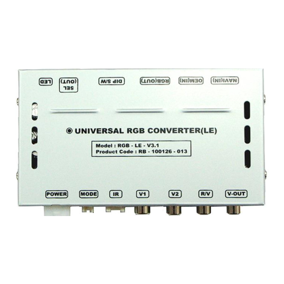
- Page 5 1.4 Exterior ⑬ ⑫ ⑪ ⑩ ⑨ ⑧ Dimension Horizontal length 129mm Vertical length 75mm Height 21mm ⑬ ⑫ ⑪ ⑩ ⑨ ⑧ ① POWER connector ② MODE connector for external button ③ IR-sensor connector ④ CVBS input V1 ⑤ CVBS input V2 ⑥...
-
Page 6: Dip Switch
2.1 DIP switch #PIN Function DIP S/W selection ON : Deactivated RGB INPUT OFF: Activated ON : Deactivated CVBS1 INPUT OFF: Activated ON : Deactivated CVBS2 INPUT OFF: Activated SET OFF ON : Skipping OEM picture OEM picture OFF: OEM activated (normal use) * Caution ON : Non-Interlace INTERLACE*... -
Page 7: Remote Controller
2.2 Remote controller Interface has no OSD-menu, there are no graphics which indicate the change of values. Function POWER & PIP No function MENU No function Making a selection ▲ Brightness higher ▼ Brightness lower ◀ Color lower ▶ Color higher SIZE : 85 * 40 * 8 (mm) -
Page 8: Power Cable Wiring Diagram
2.3 Power cable wiring diagram ⑥ ⑤ ④ FILTER & FUSE BOX ③ ② ① ① GND (black) ② N.C. ③ FM antenna ④ N.C. ⑤ ACC in +12V(red) ⑥ R-gear in +12V(gray) Blue FM antenna Orange N.C. Gray Black Blue 990mm Orange... -
Page 9: Cautions On Installation
Cautions on installation Ignition key should be taken off before starting installation, interface power connection must be the last step ▪ in installation. Power cable should be separated when connecting interface. ▪ Should be no any electronic devices or magnetic pole around installation place. ▪... -
Page 10: Installation Diagram
3.2 Installation diagram Control Box ※ Please make sure that Original the installation should be carefully conducted to avoid from the damage of a monitor B G R by ESD(Electrostatic R G B discharge) and misalignment while connecting the Offered module of a monitor with cables. -
Page 11: Installation
3.3 Installation 1. Connect sub-board to head unit. ▪ SUB Board Offered cable ▪ PORSCHE Board Connect offered FFC cable to sub- board.(LCD-IN (BOTTOM)) Offered cable... - Page 12 3.3 Installation 2. Connect Original FFC cable to sub-board. ▪ LCD Original FFC cable Original FFC cable Connect Original FFC cable to sub-board.(LCD-OUT(BOTTOM)) Original FFC cable...
-
Page 13: Photo Series
4. Photo series ▪ Position outside... - Page 14 4. Photo series ▪ Position inside (1)
- Page 15 4. Photo series ▪ Position inside (2)
Need help?
Do you have a question about the VL6-PCM21-24P and is the answer not in the manual?
Questions and answers