
Summary of Contents for EXICOM POWER SOLUTIONS 84000 Series
- Page 1 48V DC POWER SYSTEM LARGE POWER SYSTEMS - 84000 Series Indoor Power Plant User Manual...
- Page 2 Copyright © 2019 by Exicom Tele-Systems. The contents of the document are to change as per the latest design updates in the systems Contact Exicom Tele-Systems for latest copy of the document. EXICOM Tele-System Limited incepted in 1994, is a leading Telecom Power Solution Provider in India, with its corporate office in Gurgaon (Near to New Delhi) and manufacturing facilities at Solan (Himachal Pradesh) and Gurgaon (Haryana).
-
Page 3: Table Of Contents
User Manual-Power Plant Table of Contents (ID) Core Power Safety Instructions and Symbols Used ....................iii Abbreviations ............................vi Introduction ............................viii Unpacking Instructions ........................1 Power Plant Unpacking Procedure ....................1 Rectifier Unpacking Procedure ....................... 2 Product Description ..........................3 Dimensional Information ....................... - Page 4 User Manual-Power Plant RECORDS OF REVISION REVISION RELEASE DATE AUTHOR REVIEWED BY APPROVED BY Initial Issue 04. 09. 23 RICHARD AZLAN EXICOM TELE-SYSTEMS Empowering Innovation...
-
Page 5: Safety Instructions And Symbols Used
User Manual-Power Plant Safety Instructions and Symbols Used (ID) Please read the safety instructions very carefully before operation to avoid harm to the personnel or the system. The special instructions laid in this book does not include all the safety points to be observed, and are only supplement to various safety points. - Page 6 User Manual-Power Plant Safety Instructions and Symbols Used (ID) Short ircuit During operation, never short the positive and negative poles of the DC distribution unit of the system or the non-grounding pole and the earth. The power system is a constant voltage DC power equipment, short circuit will result in equipment burning and endanger human safety.
- Page 7 User Manual-Power Plant Safety Instructions and Symbols Used (ID) Sharp Objects When moving equipment by hand, protective gloves should be worn to avoid injury by sharp object. Cable Connection Please verify the compliance of the cable and cable label with the actual installation prior to cable connection.
-
Page 8: Abbreviations
User Manual-Power Plant Abbreviations (ID) ABBREVIATION DESCRIPTION Ampere Alternating Current ACDB AC Distribution Board (Panel) Ampere Hour Ultimate Capacity Batt. Battery BHMS Battery Health Monitoring System BLVD Battery Low Voltage Disconnect Controller Area Network Circuit Breaker Constant Current Constant Voltage Comm. - Page 9 User Manual-Power Plant Abbreviations (ID) ABBREVIATION DESCRIPTION Phase Neutral Power Plant Relative Humidity SMPS Switched Mode Power Supply Switched Mode Rectifiers State of Charge Std. Standard Temp. Temperature Universal Serial Bus VRLA Valve-Regulated Lead-Acid EXICOM TELE-SYSTEMS Empowering Innovation...
- Page 10 User Manual-Power Plant Introduction (ID) The Manual helps the personnel understand system, and take advantage of its capability. It includes the following information: A brief description of the unit supplied, and all its components; Operations, maintenance and repair rules, necessary for maintaining the correct operational condition of the unit;...
-
Page 11: Introduction
User Manual-Power Plant Introduction (ID) Page Intentionally Left Blank EXICOM TELE-SYSTEMS Empowering Innovation... -
Page 13: Unpacking Instructions
User Manual-Power Plant Unpacking Instructions (ID) Upon delivery, examine the consignment for possible damage caused in transit. In case the packing material or the contents inside indicates rough handling, obtain pictures of the damaged area and report it to your Exicom representative. -
Page 14: Rectifier Unpacking Procedure
User Manual-Power Plant Unpacking Instructions (ID) Rectifier Unpacking Procedure PROCEDURE: 1. Packing of four rectifiers. 2. Open the corrugated box. PROCEDURE: 3. Carefully, take out each rectifier. Packing four rectifiers. Open corrugated box. Carefully, take out each rectifier. EXICOM TELE-SYSTEMS Empowering Innovation... -
Page 15: Product Description
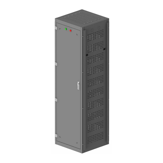
User Manual-Power Plant Product Description (ID) This section introduces all subassemblies of the power plant to user. It also gives a brief about the system functionality and its working. Dimensional Information FIGURE 2.1 - POWER PLANT OVERALL DIMENSIONS EXICOM TELE-SYSTEMS Empowering Innovation... -
Page 16: System Architecture
User Manual-Power Plant Product Description (ID) System Architecture FRONT VIEW WITHOUT FRONT DOOR EXICOM TELE-SYSTEMS Empowering Innovation... -
Page 17: Technical Specification
User Manual-Power Plant Product Description (ID) Technical Specification TABLE 2.1 - POWER PLANT TECHNICAL SPECIFICATION PARAMETERS SPECIFICATIONS System Capacity -48VDC/84kW AC Input Voltage 415VAC, Three phase/5wire (Y connection) Input Frequency 45Hz to 66Hz Output Voltage 42Vdc to 58Vdc Type of Rectifier Serenity SMR 3kW Input distribution 415VAC, Three phase/5wire (Y connection) -
Page 18: Rectifier Introduction
User Manual-Power Plant Rectifier Serenity 3000W (ID) Serenity SMR 3000W Telecom operators and infrastructure companies look for reliable, high quality, high efficiency cost effective power solutions. Exicom is proud to introduce one of the first commercially available bridgeless, dynamically and digitally controlled ultra-high efficiency rectifiers, the Serenity 3.0kW. -
Page 19: Technical Specification - Smr 3000W
User Manual-Power Plant Rectifier Serenity 3000W (ID) Internal fuse Protection DC OUTPUT 42 - 58V DC Voltage 3000 W above 185Vac Output Power 62.5 A at 48V DC Max. Current ± 5% of max. current above 10% Load Current Sharing Static Voltage 0.5% from 10% - 100% load Regulation... - Page 20 User Manual-Power Plant Rectifier Serenity 3000W (ID) 1. LED Indications LED INDICATION DESCRIPTION OFF – AC Fail ON – AC OK Green Flash – SMR Comm. OK, Sleep Mode (Slow Flash) OFF – Normal ON – AC Low/High Cut-Off, I/P AC Derating, Temp.
-
Page 21: Controller (M2000)
User Manual-Power Plant Controller (M2000) (ID) The most advanced controller platform for managing DC systems in all types of telecom environments Key Features: Powerful controller built on RTOS 2.2" high resolution color display and easy to use navigation via joystick ... -
Page 22: Technical Specification
User Manual-Power Plant Controller (M2000) (ID) M2000 Controller Technical Specifications Operating Voltage 38 - 60Vdc Power Consumption 4W (max) Dimensions (h x w x d) 43mm x 111mm x 130mm Operating Environment -20°C to 65°C; humidity: 95%RH, non-condensing Compliances 60950-1, IEC 60950-1, EN 61000-6-1/-2/-3/-4, Class B, RoHS and REACH Battery Float, boost and equalise charge modes, configurable battery temperature compensation,... - Page 23 User Manual-Power Plant Controller (M2000) (ID) Product Overview – System Controller EXICOM TELE-SYSTEMS Empowering Innovation...
-
Page 24: M2000 Physical Overview
User Manual-Power Plant Controller (M2000) (ID) M2000 Physical Overview 2. Front Panel Controls EXICOM TELE-SYSTEMS Empowering Innovation... -
Page 25: Home Screen Information
User Manual-Power Plant Controller (M2000) (ID) 3. Home Screen The Home screen displays important system parameter values and system block status. Block nomenclature and colour relations are as given below. EXICOM TELE-SYSTEMS Empowering Innovation... -
Page 26: Navigation Keys
User Manual-Power Plant Controller (M2000) (ID) NAVIGATION KEYS M2000 provides a Joystick for navigation. For Navigation towards Right push the joystick rightwards, for Left push leftwards and similarly, for Up and Down directions. To select an option or Enter, press the joystick towards the center. User can navigate through all enabled screen using the joystick. -
Page 27: Installation
User Manual-Power Plant Installation (ID) Follow the instructions carefully, before starting installation of the power plant. To be carried out by trained and authorized personnel only. Ensure the mains are well within the range. Ensure proper earthing connections. ... - Page 28 User Manual-Power Plant Installation (ID) Power Plant External Interfaces FIGURE 5.3 - POWER PLANT INSTALLATION SETUP EXICOM TELE-SYSTEMS Empowering Innovation...
- Page 29 User Manual-Power Plant Installation (ID) STEP 1: Grouting Procedure STEP 2: Grouting Preparation STEP 3: Unit Grouting Unit installation should be done on a plane surface. Attach the unit using grouting fasteners. EXICOM TELE-SYSTEMS Empowering Innovation...
- Page 30 User Manual-Power Plant Installation (ID) STEP 4: Temperature Sensor Connections 1. Access the battery temperature sensor cable (provided with the system) from the top panel and untie 2. Route the cable, through dust brush, to the battery bank or near it. STEP 5: AC INPUT Connections Before AC input connections, ensure that the respective external MCB for each phase line are in “off position”.
-
Page 31: Commissioning
User Manual-Power Plant Commissioning (ID) Follow the instructions carefully, for complete commissioning of the power plant. Before Commissioning: Make sure all the connections are tight and secure. Visually inspect cables for proper crimping of terminals. Make sure cable insulation is not damaged. STEP 1: Insert Battery Fuse 1. - Page 32 User Manual-Power Plant Commissioning (ID) STEP 6: Rectifier MCB ON 1. Sequentially turn On MCBs for each rectifier. 2. Wait 5 seconds (approx.) for each SMR to get registered. 3. Make sure Green LED for each rectifier is blinking. (This indicates successful communication with M1000). 4.
-
Page 33: Troubleshooting
User Manual-Power Plant Troubleshooting (ID) FAULT PROBABLE CAUSE CORRECTIVE ACTION MCM does not come ON. a) DC interface cable to MCM not Connect cable properly. connected. Change fuse. b) Fuse blown in DC interface card. MCM does not come ON when Fuse in the DC interface card or Replace fuse. -
Page 34: Preventive Maintenance
User Manual-Power Plant Preventive Maintenance (ID) This system is conservatively designed. It is equipped with all advance digital circuits. This system will provide trouble free service with minimum maintenance. However, a regular periodic maintenance program should be followed. Table given below provides the schedule of maintenance procedure in detail. ITEMS INSPECTION PERIOD PROCEDURE... -
Page 35: Safety Precautions
User Manual-Power Safety Precautions Plant (ID) Strange as it may seem, most fatal electrical shocks happen to people who should know better. Here are some electro medical facts that should make you think twice before taking chances. Currents between 100 and 200 mill amperes (0.1 ampere and 0.2 ampere) are fatal. Anything in the neighborhood of 10 mill amperes (0.01) is capable of producing painful to severe shock.
Need help?
Do you have a question about the 84000 Series and is the answer not in the manual?
Questions and answers