
Subscribe to Our Youtube Channel
Related Manuals for mastro ACA2001

Summary of Contents for mastro ACA2001
- Page 1 064_03 03/2006 Instructions for installation, use and maintenance GAS KITCHENS ACA2001 · ACA2002 ACA2003 · ACA2004 ACA2005 · ACA2006 · ADA2009 ACA2007 · ACA2008 ACA2009 · ACA2010 ACA2011 · ACA2016 ACJ0001 ACJ0002 ACJ0003...
- Page 2 CHARACTERISTICS Supplied by: Date: Customer Service: e-mail 064_03 - GAS KITCHENS 03/2006 2 · 22...
- Page 3 INDEX Diagram 6 Instructions for use 6.1 Safety, cleaning and repair rules Features of the appliances 6.2 Start-up Technical data 9-11 6.2.1 Lighting and disconnecting open flame burner 6.3 Lighting and shutting down a gas oven 4 Installation instructions 6.3.1 Lighting the pilot (gas oven GN 1/1) 4.1 Safety rules 6.3.2 Lighting the pilot (gas oven GN 2/1 and MAXI) 4.2 Structure, framework and safety devices of the appliances...
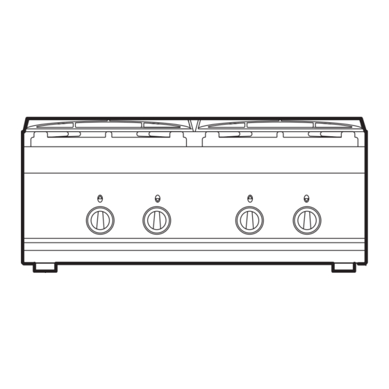
- Page 4 1 - DIAGRAM ACA20001 ACA20004 ACA20006 ACA20007 1/2" 1/2" 1/2" 100 150 ACA20001 ACA20002 ACA20005 ACA20004 ACA20006 ACA20007 1/2" 1/2" 3/4" 1/2" 6.0 kW Ø 120 mm 7.8 kW Ø 120 mm 064_03 - GAS KITCHENS 03/2006 4 · 22...
- Page 5 1 - DIAGRAM ACA20008 ACA20008 ACA20009 ACA20009 ACA20011 ACA20010 ACA20011 ACA20012 1200 1/2" 1/2" 100 150 1094 ACA20010 ACA20012 1200 1200 1/2" 1/2" 1094 1094 ACA20008 ACA20009 ACA20010 ACA20011 ACA20012 ACA2016 6.0 kW Ø 120 mm 1/2" 7.8 kW Ø 120 mm 064_03 - GAS KITCHENS 03/2006 5 ·...
- Page 6 1 - DIAGRAM ACJ00001 ACJ00001 ACJ00002 ACJ00001 ACJ00002 ACJ00002 ACJ00003 6.0 kW Ø 120 mm 7.8 kW Ø 120 mm ACJ00003 ACJ00003 1200 1094 064_03 - GAS KITCHENS 03/2006 6 · 22...
- Page 7 1 - DIAGRAM 1/2" 1/2" 100 150 1/2" 064_03 - GAS KITCHENS 03/2006 7 · 22...
- Page 8 1 - DIAGRAM 1/2" 100 150 1/2" 1094 1/2" 064_03 - GAS KITCHENS 03/2006 8 · 22...
-
Page 9: Characteristics Of The Appliances
2 - CHARACTERISTICS OF THE APPLIANCES These appliances are used for professional purposes. Installation, CAT/KAT GAS/GAZ II2H3B/P P mbar repair and use must be carried out by expert personnel. II2H3+ P mbar II2H3+ P mbar These instructions for installation are for our gas kitchens set up for II2L3B/P P mbar 0051... - Page 10 3 - TECHNICAL DATA Model Description Dimensions in mm. (LxPxH) 4 burners - 1 gas oven GN 1/1 ventilated 800 x 650 x 875 51BQ2896 4 burners with pilot flame - 1 gas oven GN 1/1 ventilated 800 x 650 x 875 51BQ2896 6 burners - 1 gas oven GN 1/1 ventilated 1200 x 650 x 875...
- Page 11 3 - TECHNICAL DATA TABLE 1 Model Gas oven Gas oven Gas oven Ø 120 Ø 120 GN 1/1 GN 2/1 MAXI Category II2H3+ Construction type Air necessary for combustion Nominal thermal power 12.0 Minimum thermal power 0.75 Overall thermal power (gas) Hour consumption G30/G31 kg/h...
-
Page 12: Installation Instructions
4 - INSTALLATION INSTRUCTIONS 4.1 Safety rules and steel (for MAXI), is in two pieces. The smoke collector is in aluminised sheet metal and the protection grill is in enamelled cast iron. • Only a local gas utility technician is authorized to carry out gas installations and connections. -
Page 13: Set-Up For Operation
4 - INSTALLATION INSTRUCTIONS 4.3.6 Smoke extraction If the type of gas indicated on the data plate of the appliance does These kitchens are type A appliances, thus no smoke extraction sys- not correspond to the gas which is present, refer to the paragraph tem is required. - Page 14 5 - SET-UP FOR OPERATION Fig. 1 5.1.4 Power check with volumetric method 5.1.6 Check of pilot flame Using a gas meter and a stopwatch, you can read the volume of gas For proper regulation, the pilot flame must surround the thermo- output per time unit.
- Page 15 5 - SET-UP FOR OPERATION Fig. 2A Fig. 2B Fig. 2C 064_03 - GAS KITCHENS 03/2006 15 · 22...
-
Page 16: Maintenance
5 - SET-UP FOR OPERATION 5.1.9 Operator training primary air. See the table "TECHNICAL DATA". • Explain and show the user how the machine works according to the instructions, and hand him this manual. 5.1.17 Replacement of nozzle of gas oven GN 1/1 (Fig. 2B) and gas oven MAXI (Fig. - Page 17 5 - SET-UP FOR OPERATION Fig. 3A Fig. 3B 5.3.3 Plug of gas oven (Fig. 2A/2B - Pos. 6) 5.3.8 Heating elements for electric oven GN 1/1 (Fig. 4B) Unscrew the fastening screws and remove the lower panel, extract Unplug the appliance from the electrical mains! the ignition wire and unscrew the screws (15).
-
Page 18: Safety, Cleaning And Repair Rules
6 - INSTRUCTIONS FOR USE 6.1 Safety, cleaning and repair rules any non-compliance with the provisions contained in this manu- 6.2 Start-up • This appliance is used for the preparation of meals at industri- al level. Usage and cleaning can be carried only by expert per- sonnel. -
Page 19: Turning The Appliance Off In Case Of Breakdown
6 - INSTRUCTIONS FOR USE Fig. 4B 6.3.3 Lighting gas oven GN 1/1 (Fig. 3B) Convection cooking In this position, heat is produced by a circular heating ele- Turn on the switch located up the line from the unit. Press the knob ment located on the back of the oven around the fan. -
Page 20: Appliance Care And Frequency Of Maintenance
6 - INSTRUCTIONS FOR USE 6.7 Appliance care and frequency of maintenance • contact with non-ferrous metals (element build up) • lack of oxygen (i.e. no air inlet, water lacking oxygen). Attention! When cleaning, carefully avoid washing the appliance with direct water jets or high-pressure 6.8.2 Warnings and advice for maintenance of stain- water! less steel appliances... - Page 21 6 - INSTRUCTIONS FOR USE 6.8.3 The 2002/96/EC (WEEE) Directive: information to users This informational note is meant only for owners of equipment marked with the symbol shown in Fig. A on the adhesive label featu- ring the technical specifications applied on the actual product (the label also giving the serial number): This symbol indicates that the product is classified, according...
-
Page 22: Appendix: Electrical Diagrams
7 - APPENDIX: ELECTRICAL DIAGRAMS ACA20006 - ACA20010 - ACA20011 Terminal board Grill heating element Commutator Bottom heating element Green indicator light Fan heating element Green indicator light Motorized fan Top heating element Thermostat Grill heating element 064_03 - GAS KITCHENS 03/2006 22 ·... - Page 23 7 - APPENDIX: ELECTRICAL DIAGRAMS ACA20007 - ACA2016 L 2 L 3 400 V 3N ~ 8.48 A R1/R2 L1 L 2 L 3 230 V 3 ~ 14.75 A R1/R2 230 V ~ 25.7 A Connected power: 5.9 kW 230/400 Terminal Indicator light (power) Switch...
- Page 24 7 - APPENDIX: ELECTRICAL DIAGRAMS ACA20007 - ACA2016 R1/R2 L1 L 2 L 3 230 V 3 ~ 14.75 A Terminal board Switch R1/R2 Thermostat Temperature limiter Green indicator light Orange indicator light Upper heating elements 230 V ~ 25.7 A Lower heating elements ACA20004 ACA20008...
- Page 25 WARNING THE MANUFACTURER CANNOT BE HELD RESPONSIBLE FOR ANY INACCURACIES IN THIS BOOKLET DUE TO COPYING OR PRINTING ERRORS. DUE TO ITS POLICY OF CONTINUAL PRODUCT IMPROVEMENT, THE MANUFACTURER RESERVES THE RIGHT TO MAKE ANY CHANGES DEEMED NECESSARY. THE MANUFACTURER CANNOT BE HELD RESPONSIBLE IF THE INSTRUCTIONS CONTAINED IN THIS MANUAL ARE NOT OBSERVED.
Need help?
Do you have a question about the ACA2001 and is the answer not in the manual?
Questions and answers