Table of Contents
Advertisement
Quick Links
Advertisement
Table of Contents

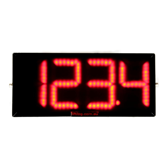
Summary of Contents for Sole Digital HBD100
- Page 1 HIBEAM Load Display Model HBD100 Installation and User Manual V1.5: 7/10/2013...
-
Page 2: Table Of Contents
CONTENTS OVERVIEW ............................4 SPECIFICATIONS ..........................5 2.1 Physical Specifications ......................5 2.2 Electrical Specifications ......................6 2.3 Communication Specifications ....................6 INSTALLATION DETAILS ........................7 3.1 Prior to Installation ......................... 7 3.2 Wiring Details .......................... 7 3.2.1 Connecting the Power Supply .................. 7 3.2.2 Connecting Load Sensor Inputs ................ - Page 3 4.5.7 Calibration (Using the 0-10V input from a ControlPro) ......... 17 4.5.8 Calibration (using the Q-Link option) ..............17 4.5.9 Resetting the Calibration ..................17 4.6 Setting Overloads ........................18 4.7 Running CheckIt Diagnostics ....................18 ROUTINE MAINTENANCE ......................20 Appendix A: Communication Protocol ....................
-
Page 4: Overview
It can accept all types of load signals (mV, V, mA, Frequency, Abus LIS Q-Link or ControlPro Volts) and when used in conjunction with Sole Digital data loggers or load limiting systems, HiBeam connects wirelessly, eliminating the need for additional cabling. -
Page 5: Specifications
2 SPECIFICATIONS 2.1 Physical Specifications Without mounting bracket With mounting bracket Overall length (mm): Overall width (mm): Overall height (mm): Weight (kg): Mounting: Screw into bracket as required. Electrical connections: 1 x 4 core cable – Active, Neutral, Fault, Fault 1 x Load cell input (prewired connector/cable to suit specified input) Detailed dimensions of the HiBeam load display are provided in Figure 1. -
Page 6: Electrical Specifications
2.2 Electrical Specifications Parameter Description Units Supply voltage Supply current Overload relay voltage limit Overload relay current limit mv load sensor sensitivity mV/V sense Input impedance of 0-10V input 1500 Ohms 24V output current Note 2 Operating temperature °C Notes: 1. -
Page 7: Installation Details
3 INSTALLATION DETAILS 3.1 Prior to Installation Before installing your HiBeam display visually inspect the unit and check that: (a) the unit is not damaged and fits together securely; (b) cables are secure; (c) the power and signal connectors are appropriate for your application. 3.2 Wiring Details For the HiBeam to operate the following must be connected as a minimum: a. -
Page 8: Connecting The Fault Output
Unless other specified at time of ordering, 7: 0-10V INPUT 1: + EXCITE your device will be provided with a 7 pin female line socket to suit the male plug on 6: +12V OUT 2: - EXCITE the device. This can be connected as shown in Figure 2. -
Page 9: Commissioning Details
4 COMMISSIONING DETAILS HiBeam is designed to be commissioned using a laptop computer. You will need a CASWA LINK-2 Bluetooth Modem and the Field Service Utility (FSU) software application loaded on a laptop. 4.1 Installing and Launching the FSU Application 4.1.1 FSU Program Installation Ensure that your computer is switched on, connected to the internet and that the minimum required software versions are installed (see Appendix B for minimum system requirements). -
Page 10: Connecting To The Device
4.2 Connecting to the Device The FSU will scan for Bluetooth enabled devices. This process takes approximately 10 seconds, when complete a list of all CASWA devices within range will be displayed. If a particular HiBeam display is not found, ensure it is powered up and press <Look again> to repeat the search. - Page 11 Press <Update> to update the HiBeam display to the latest available firmware version (recommended). The new firmware will be installed on the device. DO NOT switch off the computer or remove the LINK2 modem until this is complete – doing so may leave the display in an unrecoverable state.
-
Page 12: General Tab
4.4 General Tab 4.4.1 Setting Equipment Name The Display ID text is used to identify the HiBeam display when the FSU app searches for devices. It can be up to 18 characters long. NB: If the Display ID does not show the name of the HiBeam unit you selected when you connected to a device on the first FSU screen, power cycle the load display and try connecting again. -
Page 13: Load Input Configuration
4.5 Load Input Configuration HiBeam load displays can either be used in one of two modes: (a) Direct input : the load signal is connected directly to the display, this may require the unit to be loaded and calibrated prior to usage. All standard input types (4-20mA, mV, 0-10V, AbusQ, AbusF) can be used. -
Page 14: Using/Removing A Hoistnet Input
4.5.2 Using/Removing a HoistNet Input HiBeam displays are now compatible with CASWA HoistNet. This means that they can obtain their load signal wirelessly from any other HoistNet enabled device , eliminating the need for long cable runs between the load cell and display. They can also sum the loads from two different hoistnet devices (e.g. -
Page 15: Amplification And The Signal Indicator
Select the desired load and press <OK>. This popup box will close. A few seconds later the former box will also close. When you return to the main FSU window the name of the bound HoistNet device will be shown on the Load screen. -
Page 16: Units
If the signal is less than half of full scale, then increase the amplification by moving the gain slider to the right. 4.5.4 Units HiBeam can be configured to display the load in units of kilograms or tonnes. In tonnes mode, the display will illuminate a decimal point between the third and fourth digits (i.e. -
Page 17: Calibration (Using The 0-10V Input From A Controlpro)
After a brief pause the indicated load will show zero. Don’t be concerned if the indicated load changes or is slightly higher than zero; in this state the indicated load is very sensitive to both electrical noise and very small changes in applied load. Next, lift a known load with the crane. -
Page 18: Setting Overloads
4.6 Setting Overloads The Set Points tab lets you set the loads at which one or two load limit outputs will be triggered. In each of the Load boxes, enter the required overload in tons. For each load, select the button that corresponds to the type of fault contact being used (N/O for normally open and N/C for normally closed). - Page 19 During this process you may be asked to enter parameters (e.g. rated capacity of the hoist) to verify that critical settings have been entered and have saved correctly. Any potential issues or irregularities will be described in the CheckIt Diagnostics window. Press <Close>...
-
Page 20: Routine Maintenance
5 ROUTINE MAINTENANCE There is no routine maintenance required for this device. 20 | Page © CASWA Pty Ltd – 2013... -
Page 21: Appendix A: Communication Protocol
APPENDIX A: COMMUNICATION PROTOCOL The host sends single character commands to the device to write or query parameters. Each command must be followed by a carriage return <CR>(ASCII 13). Where the command is a query command, no arguments are sent and the device will respond with a single the requested value in ASCI text followed by a <CR>. - Page 22 Communication commands: Command Description Example Read Read BT state Send:b<CR> Returns: Rcv:3 0,Idle 1,Connect Pending 2,Waiting for Ready 3,Connected 4,Waiting for hangup Read Get Raw A-D value. Send:r<CR> Nb returns Load in tons if the display is Rcv:1234 bound to Logger or connected to an LIS. Read Read bound logger Send:l<CR>...
- Page 23 Write Write fault inverted status for output #2 Send:J20<CR> Read Read firmware version number Send:v<CR> Rcv:1.3 Read Read all parameters Send:?<CR> Reset Send:*<CR> 23 | Page © CASWA Pty Ltd – 2013...
-
Page 24: Appendix B: Fsu System Requirements
APPENDIX B: FSU SYSTEM REQUIREMENTS The minimum requirements for operating CASWA’s Field Service Utility (FSU) and Link-2 Bluetooth modem are: Laptop computer running Windows XP SP3 or later; One Spare USB port; Microsoft .NET framework 3.5. 24 | Page ©...
Need help?
Do you have a question about the HBD100 and is the answer not in the manual?
Questions and answers