Table of Contents
Advertisement
Quick Links
Advertisement
Table of Contents

Related Manuals for Nikon SB-14


Summary of Contents for Nikon SB-14
- Page 1 Nikon Speedlight INSTRUcrION MANUAL...
-
Page 2: Nomenclature
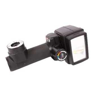
NOMENCLATURE------------------------- Wide-Flash Adapter SW-5 ® Flash head ® Shooting mode selector Sensor Unit SU-2 ® Sensor socket ® Sync/multiple flash sockets Sync Cord SC-ll ® Bracket mounting adapter ® Bracket mounting pin Trip.od/light stand socket Attachment screw slots Bracket SK-5 Tripod socket... - Page 3 f/stop indicators with wide-flash adapter (thin color-coded lines) f/stop IUl.calors f/stop scale Distance scale ASA/ISO film speed index Ready-light Bracket attachment dot Attachment screw Releasellocking wheel Handle Exposure calculator dial External power terminal ®...
-
Page 4: Table Of Contents
12-14 addition, the SB-14 is able to conserve its excess energy for the next shot when shooting subjects at close thus reducing recycling time and increasing the number... -
Page 5: Basic Operation
Plug in the sensor With the "Nikon" name facing toward ® the flash head ®, align the protrud- ing portion of the Sensor Unit SU-2 with the notched portion inside the ®;... - Page 6 BASIC OPERATION Attach the sync cord Screw end of the Sync Cord SC- 11 into either of the flash unit's sync! ® multiple flash sockets and screw the other into the camera's terminal. Some cameras do not have Note sync terminal.
- Page 7 Set the camera's shutter speed for proper syn- chronization. Set the shutter speed dial to the prop- er synchronization speed for elec- tronic flash (e.g., set the F3 to the "X" setting). For details, refer to the chart on page 11. Set the exposure calcu- -lator dial Turn the dial until the ASAIISO...
- Page 8 BASIC OPERATION-continued- - - - - - - - - ..; Set the lens' aperture ring to an approprIate number. In the example, £/4 is selected. Set the shooting mode selector Q). Turn the ring on the front of the sen- sor unit until the white index is op- posite the color corresponding to that of the £/stop...
- Page 9 Watch the ready-light soon- as the LED ready-light comes on, the flash unit is ready to fire. Take the picture. When the shutter is tripped, the flash unit fires and the picture is taken. Soon, the ready-light will light up to tell you the flash unit is recycled and ready to fire again.
-
Page 10: Controls In Detail
Once screwed in, the attachment screw can be moved freely to any position along the slot. The diagram indicates the recommended position of the attachment screw for Nikon SLR cameras and motor drives. High-Eyepoint/FGI... -
Page 11: Shutter Speed Dial
Camera type Shutter speed Nikon X ( 180), 1/60 F3 High-Eyepoint NikonFE M90 (/90), NikonFM2 X200 ( /200), 11125 Nikon FM, EL2 11125 or slower Nikkormat FT3 NikonFG* A, M90 ( /90) NikonEM* AUTO 1/80 (red Nikon F2 series 1/60... -
Page 12: Exposure Calculator Dial
-CONTROLS IN DETAIL-continued--------:----- Exposure calculator Dial exposure calculator dial on the back of the SB-14 helps you to select the usable range of speed of the film in use and the flash-to-subject distance. To set the ASA/ISO film speed, turn the dial until the... - Page 13 a subject more than 5.6m (18 ft.) flstop is fl4. On the other hand, the thin color-coded lines indicate the distance ranges when the wide-flash adapter is used: from 0.6m to 5.6m (2 to 18 13 ft.), and 0.6m to 2.8m (2 to 9 ft.), respectively. In this case, with ASAIISO 100 film, if the subject is more than 4m (13 ft.) away, only fl4 can be used.
-
Page 14: Exposure Calculator Dial
-CONTROLS IN DETAIL-continued-------- For Manual Operation Set the ASAIISO dial and simply read off the flnumber which appears directly above the flash-to-subject dis- tance; then set this aperture on your lens. example, with ASAIISO 100 and a subject 2m (approx. ft.) away, the usable flstop is fll6 without Wide-flash adapter, or fill with the wide-flash adapter attached. -
Page 15: Sensor Unit
1/125 sec., set At the M (Manual) Position for use with the Set the SU-2 to the M setting and the SB-14 operates settings, the SB-14 is manually at its maximum light output regardless of the flash-to-subject distance. In this case, you have to calcu- late the exposure manually by referring to the exposure calculator dial. -
Page 16: Ready-Light
-CONTROLS IN Ready-Light Built into the back of the SB-l4's flash head is a ready- light which comes on as soon as the flash unit is recycled and ready to fire. As an additional feature, the ready- light blinks if the flash fires at its maximum output indi- cating that the light might be insufficient for correct exposure on Automatic The warning blinks last for ap-... -
Page 17: Open-Flash Button
"strobo- scopic" effects or paint the scene with light by firing the flash repeatedly with the camera with the SB-14 connected via a sync cord set at "B," the flash will not go off even flash button is pushed. -
Page 18: Flash Head
-CONTROLS IN DETAIL-continued-------- Flash Head The SB-14's movable flash head can be tilted back up to 120 and rotated 120 to the left and 120 click-stops are provided at 30 both tilting and rotating movements. For normal shooting, point the flash head straight ahead. In this position, the light travels directly out to the subject providing the maximum amount of light possible. -
Page 19: Sync/Multiple Flash Sockets
Two standard Nikon screw-type terminals are provided on the Speedlight SB-14. Either terminal can be used to connect the SB-14 to the camera, while the other is pro- vided for connecting the SB-14 with another flash unit in series for multiple flash operation. When using the Nikon... -
Page 20: Wide-Flash Adapter Sw -S
Wide-Flash Adapter SW -5 The angle of illumination of the SB-14 by itself covers the picture angle of a 28mm wideangle lens. When the wide- flash adapter attached onto the front of the flash head, increases the illumination from 67° to 77° horizontally and 48°... -
Page 21: Tips On Automatic Flash Shooting
The sensor reads the light reflected from the something, such as the sync cord or your finger, comes between the sensor and the light reflected from the sub- ject, the SB-14 will be unable to deliver the correct ex- posure. SHOOTING- - - - -... -
Page 22: Accessories
ACCESSORIES- - - - - - - - - - - - - - DCUnitSD-7 Accepting six C -type batteries, the SD-7 is designed to be used as a power source for both the Nikon Speedlights SB-14 and SB-ll It has a neckstrap for convenient... -
Page 23: Ttl Sensor Cord
Sensor Cord SC-12 One meter long, this cord allows the SB-14 to be used with the Nikon F3 or F3 High-Eyepoint camera for auto- matic through-the-lens control of the flash exposure. When attached, the camera's shutter speed is auto- matically switched to the proper flash synchronization speed of 1/80 sec. -
Page 24: Red Eyeh
'~EDEYEn -------------------------------- "Red an optical phenomenon in which a subject's eye ," eyes appear red in photographs taken with a flash unit, is a result of the flash light's directly illuminat- ing the retina This happens when the subject looks straight into the camera on which a flash unit is mounted The effect becomes more pronounced if... -
Page 25: Optimum Battery Performance
OPTIMUM BATTERY PERFORMANCE New batteries: Between manufacturing use, all batteries exhibit care should taken to purchase (and freshest) ones possible. To help you do this, some manufacturers stamp the date of manu- facture the bottom of each camera dealer for assistance codes. -
Page 26: Specifications
SPECIFICATIONS- - - - - - - - - - - - - Guide number (ASAIISO and meters) 32 (22 with Wide-Flash Adapter SW-5) (ASA/ISO 25 and feet) 52 (36 with Wide-Flash Adapter SW Angle of coverage Horizontal: 67° (77° with SW-5) Vertical: 48°... - Page 28 (1IIIto,,) NIPPON KOGAKU K.K. reproduction in any form this booklet, in whole or in part (except for brief quotation critical articles reviews). made without Printed in Japan (82 .7.C) & written authorization from the publisher.
Need help?
Do you have a question about the SB-14 and is the answer not in the manual?
Questions and answers