
Related Manuals for WEG RUW100/PLC


Summary of Contents for WEG RUW100/PLC
- Page 1 Motors I Automation I Energy I Transmission & Distribution I Coatings RUW100/PLC Expansion Modules MOD1...MOD8 User Manual...
- Page 3 User Manual Series: MOD1...MOD8 Language: English Document: 10007363402 / 04 Publication Date: 10/2022...
- Page 4 Summary of the Revisions The information below describes the revisions made to this manual. Version Revision Description First edition Changes in the figures and tables General review Changes in the Section 5.2 EXPANSION LIMITS on page 5-1 Inclusion of MOD08...
-
Page 5: Table Of Contents
Summary 1 SAFETY INSTRUCTIONS ............... 1-1 1.1 SAFETY WARNINGS IN THE MANUAL ..................1-1 1.2 SAFETY WARNINGS ON THE PRODUCT ..................1-1 1.3 PRELIMINARY RECOMMENDATIONS ..................1-2 2 GENERAL INFORMATION ..............2-1 2.1 ABOUT THE MANUAL ........................2-1 2.2 TERMS AND DEFINITIONS USED IN THE MANUAL ..............2-1 2.3 ABOUT MODULES .......................... - Page 6 Summary 5 ELECTRICAL INSTALLATION ..............5-1 5.1 GROUNDING ........................... 5-1 5.2 EXPANSION LIMITS ........................5-1 5.3 MOD1.YZ - DIGITAL INPUTS / OUTPUTS ..................5-2 5.3.1 MOD1.00 - 24DIS ........................5-2 5.3.1.1 Digital Inputs ......................5-2 5.3.2 MOD1.10 - 24DOS ........................5-4 5.3.2.1 Digital Outputs ......................
-
Page 7: Safety Instructions
This manual describes all the functions of the MODx expansion modules, but it is not intended to explain every possible application. WEG will not take any liabilities for applications not described in this manual. This product is neither intended for applications whose purpose is to ensure physical integrity and/or life of people, nor for any other application in which a fault of the accessory may create a situation of risk to the physical integrity and/or life of people. -
Page 8: Preliminary Recommendations
For the purposes of this manual, qualified personnel are those trained in order to be able to: 1. Install, ground, power up and operate the RUW100/PLC with the different expansion modules in accordance with this manual and the legal safety procedures in force. -
Page 9: General Information
„ Help online included in the WPS/CODESYS. „ Accessory manual. „ All manuals are available for download on the WEG website - www.weg.net. 2.2 TERMS AND DEFINITIONS USED IN THE MANUAL A: amps. °C: degree Celsius. DC: direct current. mA: milliamp = 0.001 amp. -
Page 10: About Modules
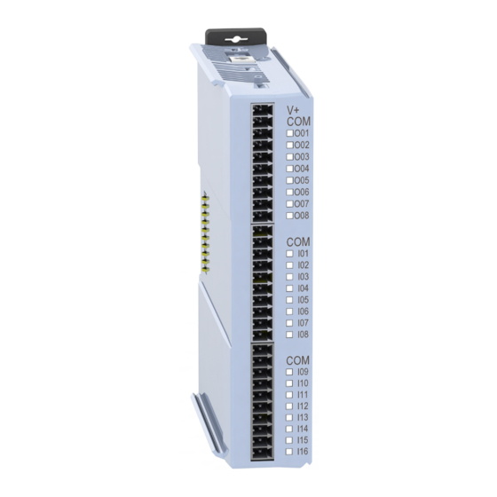
Figure 2.1: Generic module Table 2.1: Generic module Ground connection Bus for communication with the RUW100/PLC or another accessory Rail for mounting with the RUW100/PLC or another accessory Latch/bracket for mounting on 35 mm DIN rail or panel Connector pins 1 to 10 - Functionalities vary according to the model... -
Page 11: Models
General Information 2.4 MODELS 2.4.1 MOD1.yz MOD1.00 - 24DIs: model with 24 digital inputs. „ MOD1.10 - 24DOs: model with 24 digital outputs. „ MOD1.20 - 16DO/8DI: model with 16 digital outputs and 8 digital inputs. „ MOD1.30 - 08DO/16DI: model with 8 digital outputs and 16 digital inputs. „... -
Page 12: Mod8.Yz
General Information 2.4.8 MOD8.yz MOD8.00 - SCW: model capable of intelligently controlling up to four starter sets. „ This expansion has eight DOs and twelve DIs grouped into four sets (P1...P4) that are used to control contactors with error checking and alarm generation in case of failures when activating/deactivating any contactor of the starter set. -
Page 13: Mechanical Installation
To connect the MODx expansion module to an RUW100/PLC or another MODx, proceed as follows: 1. Remove the communication bus closure. 2. Insert the module into the RUW100/PLC (or other accessory) in the direction indicated by 2. 3. Reinstall the communication bus closure. -
Page 14: Din Rail Mounting
1. Move away the upper and lower latches. 2. Add the closure to the MODx. 3. Add the accessory to the RUW100/PLC (or another accessory). 4. Close the upper and lower latches again. Figure 3.2: Mechanical mounting on DIN rail... -
Page 15: Mounting With Screws
1. Move away the upper and lower latches. 2. Add the closure to the MOD1. 3. Add the accessory to the RUW100/PLC (or another accessory). 4. Fasten the accessory to the panel using the M3 screw on the top and bottom latches. -
Page 16: Accessory Dimensions
Mechanical Installation 3.4 ACCESSORY DIMENSIONS All modules have the same dimensions. 25 [0.98] 25 [0.98] 9.5 [0.37] Ø 3.1 [0.12] Figure 3.4: Accessory dimensions in mm [in] 3-4 | MOD1...MOD8... -
Page 17: Leds
Leds 4 LEDS 4.1 DIGITAL OUTPUT LED LEDs O01 to O24 represent outputs DO1 to DO24, respectively. In the MOD1, the LEDs of the digital outputs light RED whenever the digital output is active, Figure 5.2 on page 5-5. 4.2 DIGITAL INPUT LED LEDs I01 to I24 represent inputs DI1 to DI24, respectively. -
Page 18: Electrical Installation
Eletrical Installation 5 ELECTRICAL INSTALLATION The expansion boards are incorporated to the RUW100/PLC in a simple and fast way, using the "Plug and Play" concept by the user. When the RUW100/PLC is powered up, the electronic circuit identifies the number of connected expansions, the model and the firmware version of each one. -
Page 19: Mod1.Yz - Digital Inputs / Outputs
Eletrical Installation 5.3 MOD1.YZ - DIGITAL INPUTS / OUTPUTS 5.3.1 MOD1.00 - 24DIS 5.3.1.1 Digital Inputs The MOD1.00 has 24 isolated digital inputs that must be excited by an external 24 Vdc source. The inputs are bidirectional, which means the input common can be connected to either the negative or the Vdc of the power supply. - Page 20 Eletrical Installation + 24 Vcc + 24 Vcc + 24 Vcc Figure 5.1: MOD1.00 Table 5.1: MOD1.00 Name Function Not connected Common DI1 to DI8 Digital input 1 Digital input 2 Digital input 3 Digital input 4 Digital input 5 Digital input 6 Digital input 7 Digital input 8...
-
Page 21: Mod1.10 - 24Dos
Eletrical Installation 5.3.2 MOD1.10 - 24DOS 5.3.2.1 Digital Outputs MOD1.10 has 24 own isolated and protected digital outputs. The digital output circuit must be powered externally by a 24 Vdc power supply connected to the V+ (pins 1, 11 and 21) and COM (pins 2, 12 and 22) of the I/O connectors, as shown in Figure 5.2 on page 5-5. - Page 22 Eletrical Installation + 24 Vdc + 24 Vdc + 24 Vdc Figure 5.2: MOD1.10 Table 5.2: MOD1.10 Name Function Positive of DO1 to DO8 power supply Common of DO1 to DO8 power supply Digital output 1 Digital output 2 Digital output 3 Digital output 4 Digital output 5 Digital output 6...
-
Page 23: Mod1.20 - 16Do/8Di
Eletrical Installation 5.3.3 MOD1.20 - 16DO/8DI 5.3.3.1 Digital Outputs The MOD1.20 has 16 own isolated and protected digital outputs. The digital output circuit must be powered externally by a 24 Vdc power supply connected to the V+ (pins 1 and 11) and COM (pins 2 and 12) of the I/O connectors, as shown in Figure 5.3 on page 5-7. - Page 24 Eletrical Installation + 24 Vcc + 24 Vcc + 24 Vcc Figure 5.3: MOD1.20 Table 5.3: MOD1.20 Name Function Positive of DO1 to DO8 power supply Common of DO1 to DO8 power supply Digital output 1 Digital output 2 Digital output 3 Digital output 4 Digital output 5 Digital output 6...
-
Page 25: Mod1.30 - 8Do/16Di
Eletrical Installation 5.3.4 MOD1.30 - 8DO/16DI 5.3.4.1 Digital Outputs The MOD1.30 has 16 own isolated and protected digital outputs. The digital output circuit must be powered externally by a 24 Vdc power supply connected to the V+ (pin 1) and COM (pin 2) of the digital output connectors, as shown in Figure 5.4 on page 5-9. - Page 26 Eletrical Installation + 24 Vcc + 24 Vcc + 24 Vcc Figure 5.4: MOD1.30 Table 5.4: MOD1.30 Name Function Positive of DO1 to DO8 power supply Common of DO1 to DO8 power supply Digital output 1 Digital output 2 Digital output 3 Digital output 4 Digital output 5 Digital output 6...
-
Page 27: Mod2.00 - 7 Ais
Eletrical Installation 5.4 MOD2.00 - 7 AIS 5.4.1 Analog Inputs MOD2.00 has 7 differential analog inputs that can be used to measure voltage (0 - 10 V) or current (0 - 20 mA / 4 - 20 mA). Table 5.5 on page 5-11 contains the name and function of each of the pins of the Analog Input connectors. - Page 28 Eletrical Installation Figure 5.5: MOD2.00 Table 5.5: MOD2.00 Name Function AI1(+) Analog input (+) AI1(-) Analog input (-) Current measurement channel 1 AI2(+) Analog input (+) AI2(-) Analog input (-) Current measurement channel 2 AI3(+) Analog input (+) AI3(-) Analog input (-) Current measurement channel 3 Not connected AI4(+)
-
Page 29: Mod3.00 - 8 Ao (V)/4 Ao (I)
Eletrical Installation 5.5 MOD3.00 - 8 AO (V)/4 AO (I) 5.5.1 MOD3.00 - Analog Outputs MOD3.00 has eight analog outputs, four of which can be connected to voltage or current (AO1...AO4) and 4 to voltage only (AO5...AO8). 5.5.1.1 Voltage Analog Outputs MOD3.00 has 8 voltage analog outputs that can generate an output voltage from 0 to 10 V. - Page 30 Eletrical Installation Figure 5.6: MOD3.00 Table 5.6: MOD3.00 Name Function COMM Common AO1(V) Voltage analog output 1 AO2(V) Voltage analog output 2 AO3(V) Voltage analog output 3 AO4(V) Voltage analog output 4 COMM Common AO5(V) Voltage analog output 5 AO6(V) Voltage analog output 6 AO7(V) Voltage analog output 7...
-
Page 31: Mod4.00 - 7 Thermocouples
Eletrical Installation 5.6 MOD4.00 - 7 THERMOCOUPLES 5.6.1 Thermocouple Input MOD4.00 has 7 inputs for J type, K type and T type thermocouples. To connect the thermocouples to MOD4.00, just follow the example shown in Figure 5.7 on page 5-15. Table 5.7 on page 5-15 shows the name and function of each of the thermocouple connector pins. - Page 32 Eletrical Installation Figure 5.7: MOD4.00 Table 5.7: MOD4.00 Name Function TH1+ Thermocouple positive terminal 1 TH1- Thermocouple negative terminal 1 TH2+ Thermocouple positive terminal 2 TH2- Thermocouple negative terminal 2 TH3+ Thermocouple positive terminal 3 TH3- Thermocouple negative terminal 3 TH4+ Thermocouple positive terminal 4 TH4-...
-
Page 33: Mod5.00 - 4 Pt100/Pt1000
Eletrical Installation 5.7 MOD5.00 - 4 PT100/PT1000 5.7.1 PT100/PT1000 INPUT MOD5.00 allows reading up to 4 RTDs (Resistance Temperature Detectors) PT100 or PT1000 type. Figure 5.8 on page 5-17 shows how to connect three and two-wire RTDs. Obs: It is possible to invert the RTDx RL and RTDx cables in the three-wire connection without problems if they bear no identification. - Page 34 Eletrical Installation Figure 5.8: MOD5.00 Table 5.8: MOD5.00 Name Function RTD1 (-) Input for RTD1 (-) RTD1 RL Compensation cable input RTD1 RTD1 (+) Input for RTD1 (+) RTD2 (-) Input for RTD2 (-) RTD2 RL Compensation cable input RTD2 RTD2 (+) Input for RTD2 (+) Not connected...
-
Page 35: Mod6.00 - 2 Sg 5 V
Eletrical Installation 5.8 MOD6.00 - 2 SG 5 V 5.8.1 Load Cell Input MOD6.00 has two load cell inputs, where six-wire and four-wire connections are possible. Figure 5.9 on page 5-19 shows how to connect six-wire and four-wire load cells. Table 5.9 on page 5-19 contains the name and function of all MOD6.00 pins. - Page 36 Eletrical Installation Figure 5.9: MOD6.00 Table 5.9: MOD6.00 Name Function +5 V Positive of +5 V power supply (+EXC) Compensation input (+SEN) SG + Positive signal input (IN+) SG - Negative signal input (IN-) Compensation input (-SEN) Negative of 0 V power supply (+EXC) Not connected Not connected Not connected...
-
Page 37: Mod7.00 - 6 Re
Eletrical Installation 5.9 MOD7.00 - 6 RE 5.9.1 Relay Outputs MOD7.00 has six relay outputs with 1 NO contact, 1 NC contact and 1 common contact each, as shown in Figure 5.10 on page 5-20. Figure 5.10: Relay Contacts 5-20 | MOD1...MOD8... - Page 38 Eletrical Installation All relay outputs are isolated, so the common contacts between the relays are not connected. Figure 5.11 on page 5-21 shows some examples on how to connect relays to loads. Table 5.10 on page 5-21 contains the name and function of all MOD7.00 pins. 24 V 24 V 24 V...
-
Page 39: Mod8.00 - Scw
Eletrical Installation 5.10 MOD8.00 - SCW 5.10.1 MOD8.00 - Starter Manager The MOD8.00 has eight digital outputs and twelve digital inputs grouped into four groups to control up to four starter sets. The digital outputs (which activate the contactors) must be excited by an external 24 Vdc power supply. The digital inputs can be powered by another 24 Vdc power supply if necessary. - Page 40 In the "transparent" mode, the maximum current per digital output must not exceed 250 mA. Figure 5.14 on page 5-23 shows an example of connecting four different types of starters to the MOD8-SCW plugged into a RUW100. Note: Always use cables with RJ45 connectors supplied by WEG. SCW100-CM-001 SCW100-CM-002 MOD8.00-SCW...
-
Page 41: Technical Data
Technical Data 6 TECHNICAL DATA Operating Temperature: 0 °C to 45 °C (32 °F to 113 °F). „ Air relative humidity: 5 % to 90 % non-condensing. „ Degree of Protection: IP20. „ Pollution Degree: 2 (according to EN50178 and UL508C), with non-conductive pollution. „... - Page 42 Technical Data Analog Inputs: Voltage and current inputs. „ Input voltage range: 0 to 10 V differential. „ Common mode voltage limits: -10 to 10 V. „ Input current range: 0 to 20 mA. „ Resolution: 24 Bits. „ Voltage Analog Outputs: Voltage limit: 0 - 10 V.
Need help?
Do you have a question about the RUW100/PLC and is the answer not in the manual?
Questions and answers