Table of Contents
Advertisement
Quick Links
Programming
made Simple
See page 5
INDEX
Thermostat Installation
2-4
Wiring
2
Installer Menu
3-4
Test Equipment
4
Using the Thermostat
5-7
Thermostat Overview
5
User Menu
6
Thermostat Operation
6
Troubleshooting
7-8
Homeowner Help Line
8
SPECIFICATIONS
Electrical Rating:
Battery Power ..................................... mV to 30 VAC, NEC Class II, 50/60 Hz
Input-Hardwire .................................... 20 to 30 VAC, NEC Class II, 50/60 Hz
Terminal Load .......................................... 1.5 A per terminal, 2.5A maximum all terminals combined
Setpoint Range ........................................ 45° to 99° F (7° to 37° C)
Rated Differentials (@ 6°F/ Hr):
Fast
Heat (Conventional Gas / Oil / Elect) ..... 0.5°F
Cool (Central Air) ................................. 0.9°F
Heat Pump (Heat and Cool) ................ 0.9°F
Heat Pump Aux. .................................. 0.5°F
Operating Ambient .................................. 32°F to +105°F (0° to +41°C)
Display Temperature Range ....................... 32°F to +99°F (0 to 37°C)
Operating Humidity ................................. 90% non-condensing maximum
Shipping Temperature Range ................... -20°F to + 150°F (-29° to +65°C)
Thermostat Dimensions ........................... 3-3/4" H x 6" W x 1-1/8" D
NH-522NP (Non-Programmable)
Installation and Operating Instructions
Universal Thermostat
Battery Powered or Hardwired with Common
Optional Accessory: Wall
Cover-Up Plate F61-2663,
6 3/4" W x 4 1/2" H
Maximum
Thermostat Applications
Stages
Heat/ Cool
Conventional Gas, Oil, Electric
(mV and 24V), Heat only, Cool only or
Heat/Cool Systems
Heat Pump (Air Source or Geothermal)
with Aux. Heat
MERCURY NOTICE: This product does not contain
mercury. However, this product may replace a product
that contains mercury. Mercury and products containing
mercury must not be discarded in household trash.
Refer to www.thermostat-recycle.org for information
on disposing of products containing mercury.
Med
Slow
0.75°F
1.9°F
1.2°F
1.7°F
1.2°F
1.7°F
0.75°F
1.9°F
PART NO. 37-7642001
Replaces 37-7642B
2/2
2/1
1729
Advertisement
Table of Contents

Related Manuals for One Hour Comfort Sentry NH-522NP


Summary of Contents for One Hour Comfort Sentry NH-522NP
- Page 1 NH-522NP (Non-Programmable) Installation and Operating Instructions Universal Thermostat Battery Powered or Hardwired with Common Programming made Simple See page 5 Optional Accessory: Wall Cover-Up Plate F61-2663, 6 3/4” W x 4 1/2” H INDEX Thermostat Installation Maximum Thermostat Applications Stages Wiring Heat/ Cool Installer Menu...
-
Page 2: Thermostat Installation
THERMOSTAT INSTALLATION WIRING Refer to equipment manufacturer’s instructions for specific system wiring information. After wiring, see INSTALLER MENU for proper thermostat configuration. Wiring table shown are for typical systems and describe the thermostat terminal functions. Wiring will change when dedicated emergency heat is on (See Installer Menu #15). -
Page 3: Installer Menu
RC/RH Jumper Wire This thermostat electrically connects the RC and RH terminals so a jumper wire is not required. If the application provides a separate wire for RC and RH, clip the RC/RH jumper. This will isolate both terminals so they can be independently used. -
Page 4: Test Equipment
INSTALLER MENU (C0ntinued) Settings Installer’s Menu # Default Setting Description (flashing icons) (Hold Menu 8 Seconds) (Press °F – Fahrenheit Fahrenheit or Celsius °F °C – Celsius Temperature Display Adjustment: adjust the displayed “Room -5 to +5 Temperature” Continuous Display Light: keep On –... -
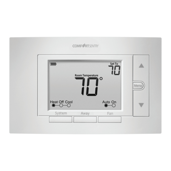
Page 5: Thermostat Overview
USING THE THERMOSTAT THERMOSTAT OVERVIEW Before you begin using your thermostat, you should be familiar with its features, display and the location/operation of the thermostat buttons and switches. THERMOSTAT BUTTONS THE DISPLAY AND SWITCHES 1.) Fan Button 8.) Next (Menu button) is used to navigate within a menu 2.) Away Button (set a frequently used 9.) Back (Fan button) is used to navigate within a menu temperature) -
Page 6: Thermostat Operation
USER MENU To customize thermostat settings, press the Menu button from the home screen. Use the buttons to highlight Settings and press Next. Use Next and Back to navigate through menu items. Press to change the setting. User’s Menu # Default Setting Settings (Press Menu button... -
Page 7: Troubleshooting
TROUBLESHOOTING Symptom Possible Cause Corrective Action 1.) Blown fuse or tripped circuit 1.) Replace fuse or reset breaker breaker 2.) Furnace power switch to OFF No Heat/ 2.) Turn switch to ON No Cool/ 3.) Furnace blower compartment 3.) Replace door panel in proper position to No Fan door panel loose or not properly engage safety interlock or door switch... - Page 8 TROUBLESHOOTING (C0ntinued) Symptom Possible Cause Corrective Action 1.) Heating system is not able to heat 1.) See corrective action for “No Heat” the space to within 10 degrees of the setpoint within 2 hours 2.) Cooling system is not able to cool 2.) See corrective action for “No Cool”...
Need help?
Do you have a question about the Comfort Sentry NH-522NP and is the answer not in the manual?
Questions and answers