
Related Manuals for Automationdirect.com SOLO SLM Series


Summary of Contents for Automationdirect.com SOLO SLM Series
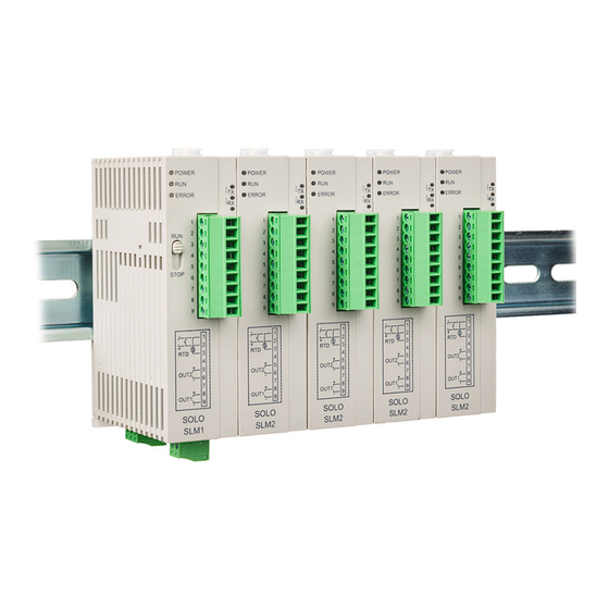
- Page 1 SOLO SLM Series Modular Temperature Controller User Manual Manual Number: SLM-USER-M...
- Page 2 ~ WARNING ~ Thank you for purchasing automation equipment from Automationdirect.com™, doing business as AutomationDirect. We want your new automation equipment to operate safely. Anyone who installs or uses this equipment should read this publication (and any other relevant publications) before installing or operating the equipment.
- Page 3 Nulle partie de ce manuel ne doit être copiée, reproduite ou transmise de quelque façon que ce soit sans le consentement préalable écrit de la société Automationdirect.com™ Incorporated. AutomationDirect conserve les droits exclusifs à l’égard de tous les renseignements contenus dans...
- Page 4 SOLO SLM Series Modular Temperature Controller User Manual Please include the Manual Number and the Manual Issue, both shown below, when communicating with Technical Support regarding this publication. Manual Number: SLM-USER-M Issue: 1st Edition Issue Date: 07/2023 Publication History Issue...
-
Page 5: Table Of Contents
Table of Contents Chapter 1: Getting Started ������������������������������������� 1–1 Manual Overview ���������������������������������������������������������������1–2 Overview of this Publication �������������������������������������������������������������������������� 1–2 Who Should Read This Manual ���������������������������������������������������������������������� 1–2 Technical Support ������������������������������������������������������������������������������������������ 1–2 Supplemental Manuals ���������������������������������������������������������������������������������� 1–2 Special Symbols ��������������������������������������������������������������������������������������������� 1–2 SOLO Modular Temperature Controller Introduction ����������1–3 General Description ���������������������������������������������������������������������������������������... - Page 6 Table of Contents Chapter 4: Controller Inputs and Outputs �������������� 4–1 Control Input Types ������������������������������������������������������������4–2 Control Output Types ���������������������������������������������������������4–3 Alarm Outputs ��������������������������������������������������������������������4–7 Chapter 5: Control Modes �������������������������������������� 5–1 PID Control �������������������������������������������������������������������������5–2 On / Off Control ������������������������������������������������������������������5–2 Ramp / Soak Control �����������������������������������������������������������5–3 Manual Control �������������������������������������������������������������������5–4 Chapter 6: Configuration Software ������������������������...
- Page 7 Table of Contents Appendix: Modbus Address Map for Ramp / Soak Control ������������������������������������������������������������������ A–1 Last Step Number �������������������������������������������������������������� A–2 Additional Cycles ��������������������������������������������������������������� A–2 Next Pattern Number �������������������������������������������������������� A–2 Ramp / Soak SV ����������������������������������������������������������������� A–3 Ramp / Soak Time ������������������������������������������������������������� A–4 1st Ed.
- Page 8 Chapter Chapter Chapter Getting Started In this Chapter��� Manual Overview ������������������������������������������������������������������ 1–2 Overview of this Publication �������������������������������������������������������������������������������1–2 Who Should Read This Manual ���������������������������������������������������������������������������1–2 Technical Support �����������������������������������������������������������������������������������������������1–2 Supplemental Manuals ���������������������������������������������������������������������������������������1–2 Special Symbols ��������������������������������������������������������������������������������������������������1–2 SOLO Modular Temperature Controller Introduction ������������� 1–3 General Description ��������������������������������������������������������������������������������������������1–3 Unpacking������������������������������������������������������������������������������������������������������������1–4 Model Number Explanation ��������������������������������������������������������������������������������1–4 SOLO Modular Temperature Controller Specifications �����������...
-
Page 9: Chapter 1: Getting Started
By Telephone: 770-844-4200 (Mon.-Fri., 9:00 a.m.-6:00 p.m. E.T.) On the Web: support.automationdirect.com Our technical support group is glad to work with you in answering your questions. If you cannot find the solution to your particular application, or, if for any reason you need additional technical assistance, please call technical support at 770-844- 4200. -
Page 10: Solo Modular Temperature Controller Introduction
Chapter 1: Getting Started SOLO Modular Temperature Controller Introduction General Description The SOLO Modular Temperature Controller is a single loop dual output temperature controller that can control both heating and cooling simultaneously. There are four types of control modes: PID, ON / OFF, Manual, and Ramp / Soak control. -
Page 11: Unpacking
Chapter 1: Getting Started Unpacking After receiving the SOLO Modular Temperature Controller, please check for the following: • Make sure that the package includes the Controller, a 249 ohm resistor and the Quick Start Guide. • Inspect the unit to insure it was not damaged during shipment. •... -
Page 12: Solo Modular Temperature Controller Specifications
Chapter 1: Getting Started SOLO Modular Temperature Controller Specifications Specifications Operating Voltage Range 21.6 to 26.4 VDC Power Consumption 5 VA Max Control Mode PID, ON/OFF, Ramp / Soak control or Manual Vibration Resistance 10 to 55 Hz, 10 m/s for 10 min, each in X, Y and Z directions Shock Resistance Max. - Page 13 Chapter Chapter Chapter Installation and Wiring In this Chapter��� Installation Considerations ���������������������������������������������������� 2–2 Mounting Instructions ����������������������������������������������������������� 2–2 Controller Dimensions ����������������������������������������������������������� 2–4 Safety Information ���������������������������������������������������������������� 2–5 Terminal Identification ���������������������������������������������������������� 2–7...
-
Page 14: Chapter 2: Installation And Wiring
Chapter 2: Installation and Wiring Installation Considerations Improper installation of the controller will greatly reduce its life. Be sure to observe the following precautions when selecting a mounting location: Warning: Failure to observe these precautions may damage the controller and void the warranty! •... - Page 15 Chapter 2: Installation and Wiring 1. Place SLM unit onto the DIN rail. 2. Lower and press firmly at the base of the unit until the DIN clip engages. SLM units rail 2–3 1st Ed. 07/2023 SOLO Modular Temperature Controller User Manual...
-
Page 16: Controller Dimensions
Chapter 2: Installation and Wiring Controller Dimensions 25.2 60.0 [0.13] [0.99] [2.36] SLM1 SLM1 SLM2 RUN/STOP Wiring and switch Model name Wiring and DIN rail clip 25.2 60.0 Model name [0.99] [2.36] [0.13] DIN rail clip I/O terminals SLM2 I/O terminals LED indicators LED indicators Mounting hole Specification... -
Page 17: Safety Information
This publication is based on information that was available at the time it was printed. At Automationdirect.com® we constantly strive to improve our products and services, so we reserve the right to make changes to the products and/or publications at any time without notice and without obligation. - Page 18 Chapter 2: Installation and Wiring Safety Information, cont’d 8. Be sure to use wires that match the thermocouple types when extending or connecting thermocouple wires. 9. Use wires with correct resistance when extending or connecting a RTD. 10. Keep the wire as short as possible when wiring a RTD to the controller and route power wires as far as possible from sensor wires to prevent interference and induced noise.
-
Page 19: Terminal Identification
Chapter 2: Installation and Wiring Terminal Identification Input and Outputs (SLM1 & SLM2 Front Terminals) Sensor Input Power Input (SLM1 Bottom Terminals) For 4-20 mA sensor input install supplied 249 resistor. DC 21.6 to 26.4 4 - 20 mA 0 - 10 VDC Install jumper when using 2-wire RTD RS-485 (SLM1 Bottom Terminals) - Page 20 Chapter Chapter Chapter LED Display and Setup Parameters In this Chapter��� LED Display ��������������������������������������������������������������������������� 3–2 Parameter List ����������������������������������������������������������������������� 3–3 Reset to Factory Default ������������������������������������������������������ 3–17...
-
Page 21: Chapter 3: Led Display And Setup Parameters
Chapter 3: LED Display and Setup Parameters LED Display 1. When power is normal, POWER LED will be on. 2. After SLM is switched on, all LEDs will be on. The communication protocol will be displayed for one second. See table below for LED values. 3. -
Page 22: Parameter List
Chapter 3: LED Display and Setup Parameters Parameter List Parameter Availablity Controller Type Control Mode Heating / Cooling ID # Parameter Name - - - P1-1 Auto Tuning ü ü ü ü ü ü ü ü ü P1-4 Proportion Band ü... - Page 23 Chapter 3: LED Display and Setup Parameters Parameter Availablity Controller Type Control Mode Heating / Cooling ID # Parameter Name P2-4 Alarm 1 High Limit ü ü ü ü ü ü ü ü ü ü ü ü P2-5 Alarm 1 Low Limit ü...
- Page 24 Chapter 3: LED Display and Setup Parameters Parameter Availablity Controller Type Control Mode Heating / Cooling ID # Parameter Name P3-15 Baud Rate ü ü ü ü ü ü ü ü ü ü ü ü P3-16 Bit Length ü ü ü ü ü ü ü ü ü ü ü ü P3-17 Parity ü...
- Page 25 Chapter 3: LED Display and Setup Parameters Note: Segmented display symbols are displayed in software and used for reference in this manual. Auto Tuning ID Number P1-1 Range: On - Auto Tuning activated Off - Auto Tuning deactivated When this parameter is set to On, the controller begins auto tuning.
- Page 26 Chapter 3: LED Display and Setup Parameters PD Control Offset ID Number P1-7 pdof Range: 0.0 to 100.0 (%) The PD Control Offset parameter is available when the P or PD control is selected [Integral Time parameter is zero]. This parameter defines the offset of the output. When the P or PD control is used, the control cannot stabilize the PV at the SV because the output is zero when the PV is equal to the SV.
- Page 27 Chapter 3: LED Display and Setup Parameters Heating Hysteresis ID Number P1-9 Range: 0.0 to 999.9 The Heating Hysteresis parameter defines the amount that the PV must go below the SV before the output turns on. This parameter is available only for On / Off control with an output programmed for heating.
- Page 28 Chapter 3: LED Display and Setup Parameters Output 2 Period ID Number P1-13 HCpd Range: 0.5 to 99 seconds The Output 1 Cooling parameter defines one output period or the duration of one on / off cycle for Output 2. hCPD Output 2 Period This parameter is available when Output 2 is programmed as a...
- Page 29 Chapter 3: LED Display and Setup Parameters PV Offset ID Number P1-16 tpof This parameter is used to add an offset value to the PV. Analog High Adjustment ID Number P1-17 CrHi The Analog High Adjustment parameter is used to adjust the actual analog output value when the output is 100%.
- Page 30 Chapter 3: LED Display and Setup Parameters Current Output -1440 -1080 -720 -360 1080 Crlo 10mA 11mA 12mA 13mA 14mA 15mA 1440 1799 2159 2519 2879 3239 3599 3959 Crlo 16mA 17mA 18mA 19mA 20mA 4319 4678 5038 5398 5758 Crlo Voltage Output 1518...
- Page 31 Chapter 3: LED Display and Setup Parameters Alarm 1 Low Limit ID Number P2-5 al1l This parameter is used to set the low limit for Alarm 1. The range varies according to other parameter values. Alarm 2 High Limit ID Number P2-6 al2h This parameter is used to set the high limit for Alarm 2.
- Page 32 Chapter 3: LED Display and Setup Parameters Input Type ID Number P3-1 Inpt This parameter defines the input signal type. Thermocouple* Type and Temperature Range Input Temperature Sensor Type Temperature Range Thermocouple TXK type -328 ~ 1472°F (-200 ~ 800°C) Thermocouple U type -328 ~ 932°F (-200 ~ 500°C) Thermocouple L type...
- Page 33 Chapter 3: LED Display and Setup Parameters Input Range High ID Number P3-3 tp-h Range: From the value of Input Range Low to 9999. This parameter defines the high limit of the PV. This is the maximum value of the operational temperature range. In operation, if the PV value is higher than the tp-h value, th PV flashes to indicate an error and the controller outputs shut off.
- Page 34 Chapter 3: LED Display and Setup Parameters Below is an example of a typical Ramp / Soak Pattern. Ramp Soak 08.00 ° 05.00 03.00 ° 03.00 02.00 05.00 ° 03.00 ° POS0 POS1 POS2 POS3 POS4 POS5 POS6 Step00 = 50° Step03 = 100°...
- Page 35 Chapter 3: LED Display and Setup Parameters Range: 7, 8 Parity ID Number P3-17 Range: None, Even, Odd Stop Bit ID Number P3-18 Range: 1, 2 Ramp / Soak Parameters Ramp / Soak SV ID Number P3-19 Range: -99.9 to 999.9 This parameter is the set point value (SV) of each Ramp / Soak step.
-
Page 36: Reset To Factory Default
Chapter 3: LED Display and Setup Parameters Reset to Factory Default Note: Resetting the Temperature Controller back to factory default erases all of the values entered by the user. Record any necessary settings before proceeding Warning: Erasing the user entered values may result in a safety hazard and system malfunction. - Page 37 Chapter Chapter Chapter Controller Inputs and Outputs In this Chapter��� Control Input Types ��������������������������������������������������������������� 4–2 Control Output Types ������������������������������������������������������������ 4–3 Alarm Outputs ����������������������������������������������������������������������� 4–7...
-
Page 38: Chapter 4: Controller Inputs And Outputs
Chapter 4: Controller Inputs and Outputs Control Input Types Thermocouple or RTD Input The SOLO Modular temperature controller can accept input from eleven types of thermocouples and two types of Platinum RTD sensors. Select the sensor type by using the parameter Input Type ( , P3-1). -
Page 39: Control Output Types
Chapter 4: Controller Inputs and Outputs Resistor Control Output Types The SOLO Modular temperature controller supports four types of control outputs depending on the model chosen. The available outputs are Relay, Voltage Pulse, Current and Linear Voltage as shown in the controller part number. SLM1 - V Output R: Relay output... - Page 40 Chapter 4: Controller Inputs and Outputs For example, when the Output Level is 60% and the Output Period is 10 seconds, the output relay is turned on for 6 seconds in the cycle. There are five parameters that define these two factors. Output Level Output 1 Level ( , P2-11) Range: 0.0 to 100%...
- Page 41 Chapter 4: Controller Inputs and Outputs Current Output The Current output generates analog DC current with a range of 4-20 mA. The maximum load resistance is 500 Ω The output current is controlled by four factors, Analog High Adjustment, Analog Low Adjustment, Output Level and Output Period.
- Page 42 Chapter 4: Controller Inputs and Outputs Linear Voltage Output The Linear Voltage output generates analog voltage from 0-10 VDC. The minimum load resistance is 1k Ω. The output voltage is controlled by four factors, Analog High Adjustment, Analog Low Adjustment, Output Level and Output Period. 10 VDC + Analog High Adjustment 1 cycle...
-
Page 43: Alarm Outputs
Chapter 4: Controller Inputs and Outputs Alarm Outputs The SOLO Modular controllers support alarm output groups ALA1 and ALA2. ALA1 and ALA2 are both SPST normally open relay outputs. See the Alarm Output Chart below: Alarm Output Types Alarm Output Mode Alarm Type Alarm Output Operation... - Page 44 Chapter 4: Controller Inputs and Outputs Alarm Output Types Cont� Alarm Output Mode Alarm Type Alarm Output Operation Lower limit standby alarm • Alarm will be enabled when the PV reaches SV and falls below SV – AL-L AL-L SV Upper limit hysteresis alarm •...
-
Page 45: Chapter 5: Control Modes
Chapter Chapter Chapter Control Modes In this Chapter��� PID Control ���������������������������������������������������������������������������� 5–2 On / Off Control ��������������������������������������������������������������������� 5–2 Ramp / Soak Control �������������������������������������������������������������� 5–3 Manual Control ���������������������������������������������������������������������� 5–4... -
Page 46: Pid Control
Chapter 5: Control Modes The SOLO controller can be configured for any of the following control modes. • PID control • On / Off control • Ramp / Soak control • Manual control PID Control Auto Tuning The SOLO Modular controllers support Auto Tuning to set up the following PID parameters automatically. -
Page 47: Ramp / Soak Control
Chapter 5: Control Modes (P1-15) dead Dead band (P1-9) (P1-10) Heating hysteresis Cooling hysteresis Heating Cooling Set point Hysteresis There are two types of hysteresis, heating and cooling. If the heating hysteresis is set, the heating output turns on using the following formula. PV <... -
Page 48: Manual Control
Chapter 5: Control Modes current pattern. The SOLO controller can execute the same Ramp / Soak pattern up to 200 times before it stops or moves to the next Ramp / Soak pattern. Manual Control In the Manual control mode, the outputs of the controller are manipulated manually by the operator. -
Page 49: Chapter 6: Configuration Software
Chapter Chapter Chapter Configuration Software In this Chapter��� PC Connection ����������������������������������������������������������������������� 6–2 Software Installation ������������������������������������������������������������� 6–3 Starting SL-SOFT ������������������������������������������������������������������� 6–6 SL-SOFT Online Help ������������������������������������������������������������� 6–6... -
Page 50: Pc Connection
Chapter 6: Configuration Software PC Connection To connect a PC to the SOLO Modular controller, you will need the following component from AutomationDirect. • SL-SOFT Configuration and Monitoring software • USB-485M (USB to RS-485 communication adapter) Use the supplied black 2-wire cable to connect the USB adapter to the SOLO Modular controller. -
Page 51: Software Installation
Software Installation To download the SL-SOFT software: From the AutomationDirect software download page (https://www. automationdirect.com/support/software-downloads?itemcode=SOLO%20 Software) Download slsoft.exe from the above URL and copy the content onto your computer at the location you prefer. Unzip the installation file to a known location. - Page 52 Chapter 6: Configuration Software You may use either the default location or choose a different location by clicking Choose and browsing to the location. Then click Install. 6–4 SOLO Modular Temperature Controller User Manual...
- Page 53 SOLO Temperature Controllers. The driver for the USB-485M Modbus adapter can be found on AutomationDirect’s website at https://www.automationdirect.com/pn/usb- 485m. If a different Modbus communication device is used, please ensure the drivers are installed prior to using SL-SOFT for the first time.
-
Page 54: Starting Sl-Soft
Chapter 6: Configuration Software Starting SL-SOFT After installing the SL-SOFT software, click on the SL-SOFT icon to start using the software. SL-SOFT allows multiple instances to run simultaneously, but care should be taken in selecting which communication ports are used because each instance must connect to its own communication port. - Page 55 Chapter Chapter Chapter Modbus Communication In this Chapter��� Modbus Protocol ������������������������������������������������������������������� 7–2 Registers ������������������������������������������������������������������������������� 7–2 Connection with the DirectLOGIC PLC ������������������������������������ 7–7 Connection with the C-more and C-more Micro HMI panels ���� 7–9...
-
Page 56: Chapter 7: Modbus Communication
Chapter 7: Modbus Communication Modbus Protocol The SOLO SLM1 controllers have a 2-wire RS-485 serial communication port. The supported protocols are Modbus RTU and Modbus ASCII. The following communication port settings are possible. Protocol Modbus RTU Modbus ASCII Network Address 1 to 247 Baud Rate 2400, 4800, 9600, 19200, 38400 bps... - Page 57 Chapter 7: Modbus Communication Address Setting Parameter R/W Description Unit: 0.1 degree. Analog input: 1EU. The read values below indicate the occurrence of errors: 8002H: Temperature not acquired yet Present temperature 8003H: Temperature sensor not connected 1000H value (PV) 8004H: Incorrect sensor type 8006H: Unable to acquire temperature, ADC input error 8007H: Unable to read/write the memory Set point (SV)
- Page 58 Chapter 7: Modbus Communication Address Setting Parameter R/W Description 1019H Temperature Filter Range R/W Range of temperature filter: 1~100, unit: 0.1°C 101AH Temperature Filter Factor R/W Setting range: 0~50 0 = Alarm 1 is disabled. Alarm 1 1020H 1- 18 = Alarm type number 0 = Alarm 2 is disabled.
-
Page 59: Modbus Protocol
Chapter 7: Modbus Communication Address Setting Parameter Description 1068H Run/Stop setting 0: Stop, 1: Run, 2: Program end, 3: Program hold 1069H 0: Heating, 1: Cooling, 2: Alarm, 3: Retransmit Control selection of Output 1 (Duplicate output Address) 106AH Control selection of Output 2 0: Heating, 1: Cooling, 2: Alarm (Duplicate Address) - Page 60 Chapter 7: Modbus Communication Input Hex - Address 1004H Input Sensor Register Value Available Range 0 ~ 50mV linear voltage input 0 ~ 50mV 4 ~ 20mA linear current input 4 ~ 20mA 0 ~ 20mA linear current input 0 ~ 20mA 0 ~ 10V linear voltage input 0 ~ 10V 0 ~ 5V linear voltage input...
-
Page 61: Connection With The Directlogic Plc
RX, WX Figure 5 Can’t write to the bit registers because the D4-450 does not support the function code 05. Modbus RTU only. See www.automationdirect.com for wiring Figure 1 and setup of the FA-ISOCON. This cable is included in the FA-ISCON... - Page 62 Chapter 7: Modbus Communication Figure 3 FA-ISOCON D2-250-1 CPU FA-24PS Connect FA-ISOCON port B to Solo controller using Belden 8102/9841 RS422/485 cable Connect FA-15HD or equivalent 15-pin connector to D2-250-1 port 2 Connect FA-ISOCON port A SOLO Modular controller to FA-15HD using RJ12 modular cable supplied with FA-ISOCON FA-15HD (order seperately)
-
Page 63: Connection With The C-More And C-More Micro Hmi Panels �7-9
Chapter 7: Modbus Communication Connection with the C-more and C-more Micro HMI panels Any of the C-more and C-more Micro HMI panels with RS-485 communications can be connected to the SOLO controllers. The C-more HMI panels have a built in RS-485 port. C-more Touch Panel SOLO Modular Controller... -
Page 64: Control
Appendix Appendix Appendix Modbus Address Map for Ramp / Soak Control In this Chapter��� Last Step Number ������������������������������������������������������������������ A–2 Additional Cycles ������������������������������������������������������������������� A–2 Next Pattern Number ������������������������������������������������������������ A–2 Ramp / Soak SV ��������������������������������������������������������������������� A–3 Ramp / Soak Time ����������������������������������������������������������������� A–4... -
Page 65: Last Step Number
Appendix: Modbus Address Map for Ramp / Soak Control Appendix: Modbus Address Map for Ramp / Soak Control Last Step Number (ID: n, P3-21) Pattern PLC Address Hexadecimal Modbus Decimal Number (Octal) Pattern 0 1040 44161 V10100 Pattern 1 1041 44162 V10101 Pattern 2... -
Page 66: Ramp / Soak Sv
Appendix: Modbus Address Map for Ramp / Soak Control Appendix: Modbus Address Map for Ramp / Soak Control Ramp / Soak SV mn, P3-19) (ID: Hexadecimal Pattern 0 Pattern 1 Pattern 2 Pattern 3 Pattern 4 Pattern 5 Pattern 6 Pattern 7 Step 0 2000 2008... -
Page 67: Ramp / Soak Time
Appendix: Modbus Address Map for Ramp / Soak Control Ramp / Soak Time mn, P3-20) (ID: Hexadecimal Pattern 0 Pattern 1 Pattern 2 Pattern 3 Pattern 4 Pattern 5 Pattern 6 Pattern 7 Step 0 2080 2088 2090 2098 20A0 20A8 20B0 20B8...
Need help?
Do you have a question about the SOLO SLM Series and is the answer not in the manual?
Questions and answers