
Summary of Contents for Coast to Coast FUN ZONE II
- Page 1 USER USER MANUAL MANUAL 824MAN001 service@coastentertainment.com P: 561.588.5200 | Fax: 561.493.2999 2201 4th Avenue N, Lake Worth Beach,FL 33461...
-
Page 2: Table Of Contents
TABLE OF TABLE OF CONTENTS CONTENTS Game Dimensions ........... Pg. 1 Before Powering On Instructions ....Pg. 2-3 Programming Menu ..........Pg. 4 Menu Options ............Pg. 5-7 Audit Menu ..............Pg. 8 Error Codes ............... Pg. 9 Connection Overview .......... Pg. 10-11... -
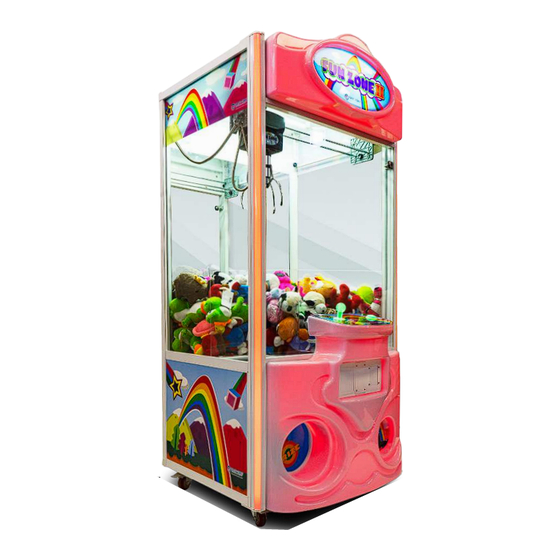
Page 3: Game Dimensions
Game Dimensions 76 in 194 cm 36 in 30 in 91.50 cm 76.50 cm Shipping Dimensions Pallet QTY Packed Dimensions Packed Weight 48”L x 48”W x 83” H (125x125x211cm) 380lbs (172 kg) -
Page 4: Before Powering On Instructions
Before Powering On Thank you for choosing the Fun Zone II crane machine system. Before turning on your new game be sure to read the following. First you should be able to find the accessories from the list below packed together with this User Manual. - Page 5 Defaults will be displayed in for your convenience, these are the factory recommended settings for start up. The settings in black can be adjusted at any time. This allows the Fun Zone II to have better percentages during high and low traffic times.
-
Page 6: Programming Menu
ProgramMing Menu Options Entering the menu, locate the small control panel inside the cabinet. You will see the volume control nob, followed by 4 buttons labeled K0 K0, K1 K1, K2 K2, K3 K3 and the power switch along the top side. Button Options: K0: Enter Audit Menu K1: Enter Crane Setting Menu... -
Page 7: Menu Options
Menu Options To enter the crane settings window press and hold the for aproximately 2 seconds. The front console display should come up with the options below. Navigate using the menu option with K1 and K2; to select a menu option use K0, and to go back or exit, use K3. 1. - Page 8 Menu Options continued 4. 4. Claw Strength Max - 1-48V Grabbing power should not be better not lower than 30V. Default set to 35V Min - 1-24V Retaining power, can set automatically from the section. Default set to 15V Change time - 0.0 - 10s Holding time in voltage will be dropping smoothly in between grabbing power and retaining power.
- Page 9 Menu Options continued 14. Attract Music Music Select 1-7 / Yes Demo music setting, 7 sounds for option. 15. Bonus Coin Yes / No Bonus credit setting. 16. Winner Show Off Yes / No Winner game not winning function on or off. 1 Chance Winner game not winning extra free game.
-
Page 10: Audit Menu
Audit Menu Press to enter Audit menu options, once in press as prompted on screen to leave. 1. Total Income Total of credits inserted into machine. 2. Current Income Total credits insterted since last cleared. 3. Coin 1 Income Total income on Coin 1 since last cleared. 4. -
Page 11: Error Codes
Error Codes Error codes will show at the bottom of the display at all times. Error Code Fixes Coin 1 Error 1. Make sure the mechanism is not broken 2. Check the coin stuck Coin mech set in “No” mode Reset machine to default setting by turning the game off then pressing K0 + K3 and Memory Error powering back on... - Page 12 Error Codes Continued Error Code Fixes Back SW error Gantry Back Stop Switch Error 1. Check for loose cable at switch. 2. Make sure switch is wired properly (Signal line to NO) 3. Replace Switch Upper SW error Claw Up Stop Switch Error 1.
-
Page 13: Connection Overview
Connection Overview Notes: 1. Make sure the opposite wall from the sensor has the black aphotic paint sticker, or the sensor will not work properly. If the following errors persist contact customer service. A. Red light always on or blinking B. - Page 14 Connection Overview Connector Usage Color Connector Usage Color Yellow Blue Blue Green Black P1 1 Yellow Power Supply Green LCD Display Orange Brown Black Black Brown White Voltage Meter Speakers Black Gray Connector J3 off stage one...
- Page 15 USER NOTES...
- Page 16 www.coasttocoastcranes.com www.coasttocoastcranes.com FOLLOW US ON SOCIAL FOLLOW US ON SOCIAL...
Need help?
Do you have a question about the FUN ZONE II and is the answer not in the manual?
Questions and answers