Table of Contents
Advertisement
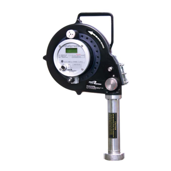
INSTRUCTION MANUAL
for PMS (Portable Tank Measuring System)
Portable Oil-Water Interface Detector
and Temperature Gauging
Model T2000-TFC-02
Gas-Tight(Closed) Type
Benefits of T2000-TFC-02
Portable – one unit used for all tanks
Economical and affordable
Cargo contents validation
High Accuracy & Response Performance
Easy Installation & Operation
Easy Maintenance
Environmental Pollution Prevention
Perfect Isolation of Hazardous Gas
Determines Interface, Ullage and
temperature (3 – in – 1)
MODEL : T2000-TFC-02
Advertisement
Table of Contents

Summary of Contents for TKT T2000-TFC-02
- Page 1 PMS (Portable Tank Measuring System) Portable Oil-Water Interface Detector and Temperature Gauging Model T2000-TFC-02 Gas-Tight(Closed) Type Benefits of T2000-TFC-02 Portable – one unit used for all tanks Economical and affordable Cargo contents validation High Accuracy & Response Performance Easy Installation & Operation...
-
Page 2: Table Of Contents
4. All Kinds of TANKTECH Portable Measuring System. 5. Installation Chart for TANKTECH Portable Measuring System. 6. Three Functions. 7. Specification for Portable Oil/Water Interface Detector. (Model : T2000-TFC-02) 8. Operating Process for Portable Oil/Water Interface Detector. (Model : T2000-TFC-02) 9. Troubleshooting for Portable Oil/Water Interface Detector. -
Page 3: Useful Measuring Jobs On Deck Of Tanker And Applicable Rules
SHEET NO. : TKT-TFC-02 (REV. 2-3) -
Page 4: Type Of Portable Equipment For Ibc Bch Code
Alternatively an indirect device which does not penetrate the tank shell and which is independent of the tank may be used. Examples are weighing of cargo, pipe flow meter. SHEET NO. : TKT-TFC-02 (REV. 2-3) - Page 5 27 September 1982 where the requirements of 4.1 & 4.2 are met by a shutdown valve which operates automatically. 3.10 Gauging for individual substances Types of gauging for individual substances are shown in column “j” of the summary of minimum requirements in chapter VI. SHEET NO. : TKT-TFC-02 (REV. 2-3)
-
Page 6: All Kinds Of Tanktech Portable Measuring System
T2 000-T F S-01 L IG H T O N MODEL T2 000 -TFC-02 MFG . NO MFG . NO MFG . DATE MFG . DATE MAD E IN K OREA M ADE I N KOREA SHEET NO. : TKT-TFC-02 (REV. 2-3) -
Page 7: Installation Chart For Tanktech Portable Measuring System
Interface Detector & Adaptor Gas-tight Type Gas-tight Type Restricted Type T2000-TFC-01 T2000-TFC-02 T2000-TFS-01 T2000-TSS-01 T2000-TLS-01 T2000-TOS-01 T2000-TSS-02 T2000-TPG-01 TVC-01 TVC-02 TVC-04 6. Three Functions 1. Detection of Ullage 2. Detection of Interface 3. Temperature measurement SHEET NO. : TKT-TFC-02 (REV. 2-3) -
Page 8: Specification For Portable Oil/Water Interface Detector
9 Volt (MODEL : MN1604) Intrinsically safe type Ex ia IIB T4 7-3. Material MODEL : T2000-TFC-02 ( Body ) ----------------- : Aluminum casting ( JIS – AC4C-T6 ) 7-4. Coating IN / OUT SIDE ----------------------------------------- : Epoxy nylon coating COLOR -------------------------------------------------- : Black THICKNESS ( IN/OUT SIDE ) --------------------- : 80mic. -
Page 9: Operating Process For Portable Oil/Water Interface Detector
Warning : When wrong use of equipment may cause body harm to user. Caution : When wrong use of equipment may cause damage to the set. 8-3. Application for model : T2000-TFC-02 Model : T2000-TFC-02 SHEET NO. : TKT-TFC-02 (REV. 2-3) - Page 10 7. Buzzer : Audible & distinguishable sound of Gas, Oil & Water 8. LCD Display 9. Display Panel 10. Power Switch 11. Tape Protection Device 12. Sensor Probe 13. Frame (Storage Barrel) 14. Grounding clamp for static discharge TA NKTECH Fig 1. Location & Function SHEET NO. : TKT-TFC-02 (REV. 2-3)
- Page 11 Fig 3. For the accurate measurement, it is desirable that the battery is replaced immediately after the warning is displayed. The battery should be replaced in non-hazardous area. Fig 3. Low battery warning SHEET NO. : TKT-TFC-02 (REV. 2-3)
- Page 12 And the electric power for sensors travels to the probe through the steel tape. Also, the steel tape is strong enough to bear the live load of probe. Therefore it has the function as protector of the electric wires from breaking. Fig 4. Detail electric wire & Tape SHEET NO. : TKT-TFC-02 (REV. 2-3)
- Page 13 2. Detection : Be determined the output of the receiver sensor, according to the acoustic impedance of the oil and the gas. The medium is between the transmitter and the receiver Ullage Detection Point Gas Zone Oil Zone Ultrasonic Sensor Fig 6. Ullage detection point SHEET NO. : TKT-TFC-02 (REV. 2-3)
- Page 14 The reason for using RTD is explained below first with a linear change in resistance over temperature. Gas Zone Oil Zone Temperature Detection Point Temperature Sensor Oil Zone Water Zone Fig 8. Temperature detection point SHEET NO. : TKT-TFC-02 (REV. 2-3)
- Page 15 CARGO TANK BOTTOM DIMENSION (UNIT : mm) MODEL REMARK H3=H+H1+H2+320 TVC−02 1. * FILL OUT BLANK BY CUSTOMER SCOPE 2. DIMENSION H2 IS WITHOUT GASKET(Gasket is Customer Scope) Fig 9. Reading Ullage & Interface SHEET NO. : TKT-TFC-02 (REV. 2-3)
- Page 16 When sensing part descend by reel, display part emits beep and indicates the surrounding environment of the oil storage tank on the LCD. MODEL TVC-02 Shut On/Off valve (Gauging Station) installed on tank top. Fig 10. Direction for Open & close of cap Fig 11. Detail of seal SHEET NO. : TKT-TFC-02 (REV. 2-3)
- Page 17 Position of detection Beep LCD Indication Intermittent beep Gas zone --- --- --- --- Frequent beep Oil zone - - - - - - - - - - Continuous beep Water zone ------------------ WATER SHEET NO. : TKT-TFC-02 (REV. 2-3)
- Page 18 4. Pull the Deck Valve lever to open position (in parallel with pipe). OPEN CLOSE Fig 14. Open handle position 5. Pull the Deck Valve lever to open position (in parallel with pipe). Fig 15. Reel handle breaker SHEET NO. : TKT-TFC-02 (REV. 2-3)
- Page 19 8. Further down in the slop tank as it senses water, display changes to "WATER" on LCD and buzzer emits continuous beep start reading the scale the transparent window. Please read out above line of tape reading bar. Fig 17. View of Ullage, Interface read out point SHEET NO. : TKT-TFC-02 (REV. 2-3)
- Page 20 Sensor probe will be inserted to the protection pipe during tape rewinding and this protection device will be completely protected by the tape. SENSOR PROBE STORAGE BARREL TAPE PROTECTION DEVICE FIX GUIDE TVC-02 BALL VALVE Fig 19. Tape protection device SHEET NO. : TKT-TFC-02 (REV. 2-3)
-
Page 21: Troubleshooting For Portable Oil/Water Interface Detector
3.6.3 soldering. 3.7 To remove wire from connector, push the latch pin with jewel screwdriver and pull out wire from plastic connector. 3.8 Use Ohm meter to check continuity between tape wires and connector. SHEET NO. : TKT-TFC-02 (REV. 2-3) - Page 22 ♦ Check the wiper in OFF Position before lowering tape. ♦ Loosen the TEFLON / VITON gland seal located at the top of the Storage Tube to allow more freedom of movement for the tape. SHEET NO. : TKT-TFC-02 (REV. 2-3)
Need help?
Do you have a question about the T2000-TFC-02 and is the answer not in the manual?
Questions and answers