
Related Manuals for Srne HF4835U60-H


Summary of Contents for Srne HF4835U60-H
- Page 1 SOLAR INVERTER CHARGER Product Manual Product Type HF4835U60-H | HF4850U80-H Solar Energy Storage Inverting & Control All-In-One Machine...
- Page 2 Important Safety Instruction Please maintain the manual for reference in the future The manual comprises all safety, installation and operation instruction for HF -H Solar Energy Storage and Inverting Control All-in-one Machine. Before installation and use, please carefully read all instructions and notices in the manual. There is unsafe voltage inside the all-in-one machine.
-
Page 3: Table Of Contents
Table of Contents 1. Basic Information ........................4 1.1 Product overview and characteristics......................... 4 1.2 Basic system introduction ............................. 5 1.3 Product characteristics ..............................6 1.4Dimension drawing ................................7 2. Installation Instruction ....................... 8 2.1 Installation notice ................................8 2.2 Wire specification and breaker type ........................... 9 2.3 Installation and Wiring .............................. -
Page 4: Basic Information
1. Basic Information 1.1 Product overview and characteristics HF -H series is a new type of mixed solar energy storage inverting & control all-in-one machine integrating solar energy storage & municipal power charge storage and AC sine wave output. It adopts DSP control and advanced control algorithm to achieve characteristics of high response speed, high reliability and high industrial standard. -
Page 5: Basic System Introduction
can supply power to the load at the same time (if there is no battery, the commercial power must be connected). When the battery is full, it can also enter the mixed load mode, which can make full use of the photovoltaic energy. -
Page 6: Product Characteristics
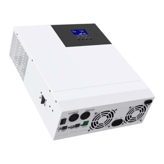
1.3 Product characteristics Overload protector Dry contact port ⑨ ON/OFF rocker switch Cooling fan ② ⑩ ACi nput port Battery port ③ ⑪ AC output port Cooling fan ④ ⑫ Grounding screw hold PV port ⑤ ⑬ RS485-2 communication port Touch the key lightly ⑥... -
Page 7: Dimension Drawing
1.4Dimension drawing Solar Energy Storage Inverting & Control All-In-One Machine... -
Page 8: Installation Instruction
2. Installation Instruction 2.1 Installation notice Before installation, please carefully read the manual and get familiar with the installation step. Take care while installing the battery. When installing the lead-acid liquid battery, it is required to wear goggles. Any body part contacting the battery acid must be washed with clear water in time. Don ’t place any metal object beside the battery to prevent short circuit of the battery. -
Page 9: Wire Specification And Breaker Type
Recommended wire Maximum PV input Recommended types Type diameter current of air switchor breaker HF4835U60-H 2P—25A /10AWG HF4850U80-H 2P—25A /10AWG Note: the voltage in parallel shall not exceed maximum PV input open-circuit voltage. Please refer to the table below for recommended AC input wire diameter and switch: ... -
Page 10: Installation And Wiring
Maximum bypass Type types of air switch wire diameter output output current or breaker current HF4835U60-H 2P—40A 10mm /7AWG HF4850U80-H 2P—63A 10mm /7AWG Note: the wire diameter is only for reference. In case of long distance between photovoltaic array and all-in- one machine or between all-in-one machine and battery, use thicker wire to reduce voltage drop and improve system performance. - Page 11 Step 2: Remove the terminal protection cover Step 3: wiring AC input/output wiring method: ① Before AC input/output wiring, disconnect the external breaker at first and then confirm whether the cable used is thick enough. Please refer to chapter “ 2.2 Wiring Specification and Breaker type”; ②...
- Page 12 : Ground L:Live N:Neutral ③ Correctly connect AC output wire in accordance with cable sequence and terminal position shown in the figure below. Please connect the ground wire at first, and then live wire and null wire. The ground wire is connected to the ground screw hold through Oshaped terminal.
- Page 13 PV+ positive input pole PV1- negative input pole BAT wiring method: ① Before wiring, disconnect external breaker at first, and then confirm whether the used cable is thick enough. Please refer to chapter “ 2.2 Wiring Specification and Breaker Type ” . BAT wire shall be connected with the machine via O-shaped terminal.
- Page 14 Step 4: inspect whether the wires are correctly and firmly connected, especially whether the positive and negative input poles of the battery are correct, whether the positive and negative input poles of PV are correct, whether AC input is inaccurately connected to AC output terminal. Step 5: install protective cap of terminal Step 6: Start all-in-one machine At first close the breaker at the battery end, and then press the rocker switch at the lower left side of the machine...
-
Page 15: Operating Mode
3.Operating Mode 3.1 Charge mode 1. Photovoltaic priority: in photovoltaic priority charge mode, mains charge is started only when photovoltaics is out of work. Make full use of solar energy for power generation in the daytime and transfer to the mains supply for charge to maintain electric quantity of the battery. -
Page 16: Output Mode
3.2 Output mode Photovoltaic priority mode: Photovoltaic and battery supply power to the load. With diversified charge mode and optional output mode, when photovoltaic priority mode is selected, the green solar energy can be used as far as possible so as to achieve energy conservation and emission reduction. It switches to mains supply when the photovoltaics is invalid. -
Page 17: Operation Instruction For Lcd Screen
4. Operation Instruction for LCD Screen 4.1 Operation and display panel 4.2 Introduction to operation keys Function Key Description Enter/exit setting menu Last option DOWN Next option Confirm/enter option under setting menu 4.3 Introduction to indicator light Indicator light Color Description Constant on: mains supply output AC/INV... -
Page 18: Introduction To Lcd Screen
4.4 Introduction to LCD screen Icon Function Icon Function Indicating that AC input end Indicating that inverter circuit is in has been connected to working. power grid Indicates that the AC input Indicating that the machine is in mode in APL mode (wide mains supply bypass work mode voltage range) Indicating that PV input end... - Page 19 Indicating that present Indicating that buzzer is not battery type of the machine enabled is lithium battery Indicating that current Indicating alarm of machine battery type of machine is lead-acid battery Indicating that the battery is Indicating that the machine is in in charge state.
-
Page 20: Setting Parameter
Real-time data view method In LCD main screen, press keys “UP” and “DOWN” to turn page and view different realtime data of the machine. Middle Page Left Parameter of Screen Parameter of Right Parameter of Screen Screen Battery input voltage Output voltage PV temperature PV output KW... - Page 21 No. of Name of Setting Description Parameter Parameter Option Exit [00] ESC Exit from setting menu At photovoltaic priority mode, when the photovoltaics is invalid or the battery values are [01] SOL lower than the parameter 【04】setting value, it shall switch to AC power. Work priority [01] UTI At AC priority mode, it switches to inverter only...
- Page 22 No. of Name of Setting Description Parameter Parameter Option Maximum [07] 60A Setting range 0~80A; default Charge current [08] USE For user-defined, all battery parameters can be set. Sealed lead-acid battery, constant voltage charge [08] SLd voltage 57.6V, float charge voltage 55.2V. For vented lead-acid battery, charge voltage at [08] FLd constant voltage is 58.4V and float charge voltage...
- Page 23 No. of Name of Setting Description Parameter Parameter Option So as to battery undervoltage alarm point, when the Battery battery voltage is lower than the judgement point, [14] 44V undervoltage an undervoltage alarm is given out and no turnoff is default alarm point output.
- Page 24 When the automatic restart after overload is enabled, if the output is turned off upon overload, [23] ENA output is restarted by the mains after 3min delay. default The machine shall not restarted after 5 times of restarts. When automatic restart after overtemperature [24] DIS is disabled, if the output machine is turned off Automatic...
-
Page 25: Battery Type Parameters
Battery type parameters For Lead-acid Battery : Battery type Sealed lead Colloidal lead Vented lead User-defined acid battery acid battery acid battery (USE) Parameters (SLD) (GEL) (FLD) Overvoltage disconnection voltage 40~60V Equalizing charge voltage 58.4V 56.8V 59.2V Adjustable 40~60V Boost charge voltage 57.6V 56.8V 58.4V... - Page 26 For Lithium Battery : Lithium Lithium Lithium Ternary Ternary Battery type iron iron iron User- lithium lithium phosphate phosphate phosphate defined battery battery Parameters battery battery battery (USE) (N13) (N14) (L16) (L15) (L14) Overvoltage disconnection voltage Equalizing charge 40~60V voltage (Adjustable) 53.2V 57.6V...
-
Page 27: Other Function
5.Other Function 5.1 Dry node function Working principle: this dry node can control the switch of diesel generator to charge the battery. ① Under normal conditions, in this terminal, NC-N point is closed and NO-N point is opened; ② when the battery voltage reaches the low-voltage disconnection voltage point, the coil of the relay is energized and NO-N point is closed and NC-N point opened. -
Page 28: Protection
6.Protection 6.1 Protection function Protection Note Function Current limiting When the charge current of the configured PV array exceeds the rated protection current of PV, it will be charged at the rated current. At night, because the battery voltage is greater than that of the PV Anti-reverse charge module, the battery shall be protected against discharge through the protection at night... -
Page 29: Meaning Of Fault Code
6.2 Meaning of fault code Affecting Fault Code Fault Name Note output or not 【01】 BatVoltLow Battery undervoltage alarm Average overcurrent software 【02】 BatOverCurrSw protectionforbattery discharge 【03】 BatOpen No connection alarm of battery 【04】 BatLowEod Stop discharge alarm for battery undervoltage 【05】... -
Page 30: Some Fault Troubleshooting
6.3 Some fault troubleshooting Fault Solving Measures Check whether the battery air switch or PV air switch is closed; No display on screen whether the switch is in "on" state; press any key on the screen to exit from the screen sleep mode. Charge battery overvoltage Measure whether the battery voltage exceeds 60V, and protection... -
Page 31: System Maintenance
7.System Maintenance In order to maintain the optimum and permanent operation performance, it is suggested to check the following items semiannually. Confirm that the air flow around the all-in-one machine will not be blocked. In addition, remove any dirt or debris from the radiator. -
Page 32: Technical Parameter
8. Technical Parameter Model HF4835U60-H HF4850U80-H AC mode Rated input voltage 110/120Vac Input voltage range (90Vac-140Vac) Frequency 50Hz/ 60Hz (auto-sensing) 47±0.3Hz ~ 55±0.3Hz (50Hz); Frequency range 57±0.3Hz ~ 65±0.3Hz (60Hz); Overload/short- circuit protection Breaker Efficiency >95% Conversion time 10ms (Typical value) - Page 33 Maximum charge current Charge current error ± 5Adc Charge voltage range 40–60Vdc Short-circuit protection Breaker and blown fuse Breaker specification Overcharge protection Turn off charge after 1min alarm Solar charge Maximum PV open- circuit voltage 450Vdc 500Vdc PV operation voltage range 120-450Vdc 120-500Vdc MPPT voltage range...
Need help?
Do you have a question about the HF4835U60-H and is the answer not in the manual?
Questions and answers