Maxsys LCD4501, LCD4501T - Keypad Installation Manual
- Installation instructions (2 pages)
Advertisement
Introduction
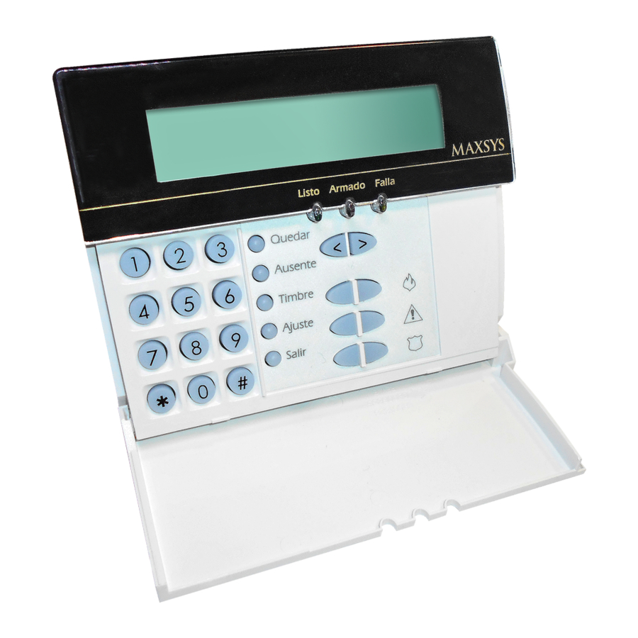
The LCD4501 keypad, for use on Maxsys PC4010/4020, presents system status via a 32-character liquid crystal display.

Specifications
- Connects to control panel via 4-wire Combus
- Current Draw: 50mA (from Combus)
- Optional tamper version (LCD4501T)
- Five programmable function keys
- Ready (green), Armed (red) and Trouble (yellow) status lights
- LCD4501R/LCD4501RT with red bezel also available (Canada only)
Installation
Unpacking
The LCD4501 package includes the following parts:
- One LCD4501 keypad
- Four mounting screws
- One keypad inner door label
- One set of Fire, Auxiliary and Panic key labels
Mounting
The Keypad should be mounted where it is accessible to designated points of entry/ exit. Once a dry and secure location is selected, perform the following steps to mount the keypad:
- Remove the keypad backplate by loosening the screw located at the base of the unit.
- Secure the keypad backplate to the wall in the desired location. Use the screws provided.
Before mounting the keypad to its backplate, complete keypad wiring.
Please refer to the System Installation Manual for information on limitations regarding product use and function and information on the limitations as to liability of the manufacturer.
Wiring
Before beginning to wire the unit, ensure that all power (AC transformer and battery) is disconnected from the control panel.
To complete keypad wiring, connect the four Combus wires (red, black, yellow and green) to the keypad terminals (R B Y G). Consult the diagram below:

Applying Power
Once all wiring is complete, apply power to the control panel. Connect the battery leads to the battery, then connect the AC transformer. For more information on control panel power specifications, see the control panel Installation Manual.
NOTE: Do not connect the power until all wiring is complete.
Enrolling the Keypad
Once all wiring is complete, the module must be enrolled on the system. For instructions on enrolling keypads, see your PC4010/4020 Installation Manual.
Programming the Keypad
Various programming items pertain to the operation of the keypad. See your PC4010/4020 Installation Manual for descriptions of the following programmable features:
- Partition and Global keypad options
- Keypad time-out
- Keypad blanking
- Fire, Auxiliary and Panic Keys
- Keypad lockout
- Keypad tampers (this feature must be enabled if using tamper version keypads)
- Function keys: the five function keys are programmed as Stay Arm, Away Arm, Door Chime Activation, Reset and Quick Exit by default. To alter these keys from their default settings, see the list of available options in the PC4010/ 4020 v3.0 Installation Manual.
NOTE: Function keys are only available when used with PC4010/4020 v3.0 and higher.
©1999, 2001 Digital Security Controls Ltd., Toronto, Canada
Technical Help Desk (Canada & US) 1-800-387-3630 • www.dsc.com
Printed in Canada 29002887 R002

Documents / Resources
References
Download manual
Here you can download full pdf version of manual, it may contain additional safety instructions, warranty information, FCC rules, etc.
Download Maxsys LCD4501, LCD4501T - Keypad Installation Manual
Advertisement

Need help?
Do you have a question about the LCD4501 and is the answer not in the manual?
Questions and answers