Advertisement
Introduction
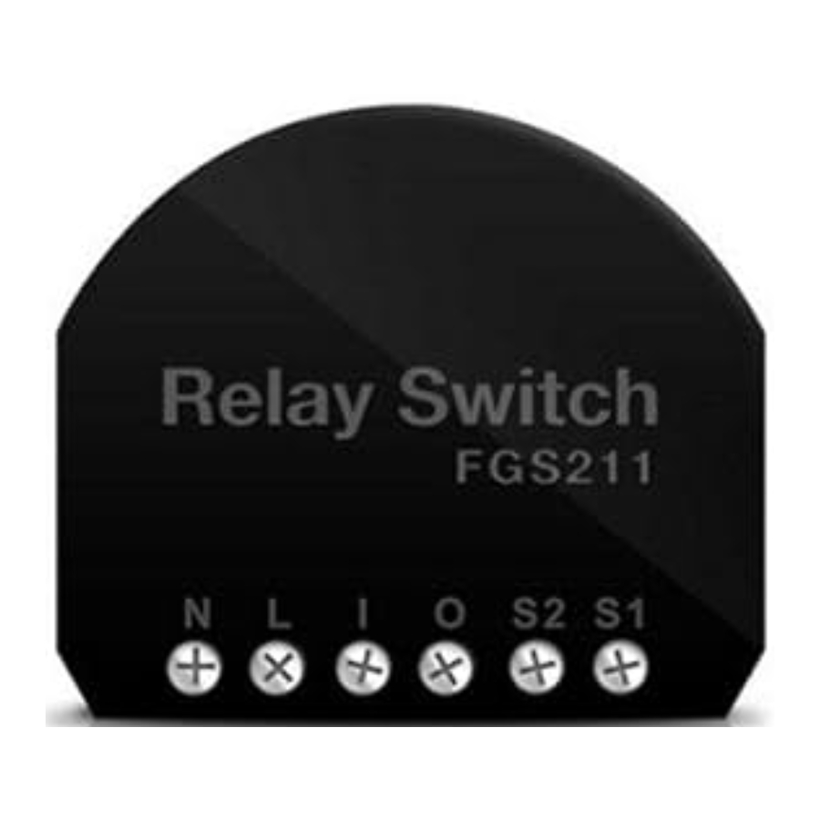
Remotely Controlled Relay Switch of FIBARO system is designed to operate in a wall switch box, wall socket box or in locations where the control of an electric device (up to 3kW) is needed. It is also possible to send a signal to any system that is to be integrated with Fibaro system.
Specifications
Power supply
110 - 230 V AC ±10% 50/60Hz
24-60V DC ±10%
Rated load current for AC 16A / 230V 50/60Hz output
Rated load current for DC 16A / 30V output
Output circuit power (resistive load) 3 kW
Comply with EU standards
EN 55015
EN 60669-2-1
Temperature limits 105°C
Operational temperature 0 - 40°C
For installation in boxes Ø ≥ 50mm
Radio protocol Z-Wave
Radio Frequency 868 MHz
Range
up to 50 m outdoors
up to 30 m indoors
(depending on building materials)
Dimensions (H x W x D)
15 x 42 x 38 mm
Electricity consumption < 0,25W
* In case of load other than resistive, pay attention to the value of cosᵠ and if necessary apply load lower than the rated load.
Technical Information
- Controlled by FIBARO system devices or any Z-Wave controller.
- Microprocessor control
- Executive elements: relays.
- The device may be operated by mono-stable and bi-stable push-buttons.

Danger of electrocution! All works on the device may be performed only by a qualified and licensed electrician. Observe national regulations.
Danger of electrocution. Even when the device is turned off, voltage may be present at its terminals. Any works introducing changes into the configuration of connections or the load must be always performed with disconnected voltage (disable the fuse).
 TIPS
TIPS
- Do not connect the device to loads exceeding recommended values.
- Connect only in accordance with the diagram presented in the manual. Improper connections may be dangerous.
GENERAL INFORMATION ABOUT FIBARO SYSTEM
FIBARO is a wireless system, based on Z-Wave technology. FIBARO provides many advantages when compared to similar systems. In general, radio systems create a direct connection between the receiver and transmitter. But the radio signal is weakened by various obstacles located on its path (apartment walls, furniture, etc.) and in extreme cases it fails to transfer required data. The advantage of FIBARO system is that its devices apart from being transmitters and receivers of signals, they are also a signal "duplicators". When a direct connection path between the transmitter and the receiver can not be established, the connection may be achieved through other intermediate devices.
FIBARO is a bi-directional wireless system. It means that the signal is not only sent to the receivers but also the receivers send the confirmation of its reception. This operation confirms their status so to check whether they are active. Safety of the FIBARO system transmission is comparable to the safety of transmission in data bus wired systems.
FIBARO operates in the free band for data transmission at 868MHz frequency. Every FIBARO system has its own unique identification number (home ID). Therefore, it is possible to operate two or more independent systems in one building without any interference.
Although Z-Wave is quite new technology, it has already become recognizable and officially binding standard, similarly to Wi-Fi. Many manufacturers in various industries offer solutions based on Z-Wave technology, guaranteeing their compatibility. This means that the system is open and it may be extended in the future. Find more information at www.fibaro.com.
FIBARO generates a dynamic network structure. After FIBARO system is switched on, the location of its individual components is automatically updated in real-time through status confirmation signals received from devices operating in a "mesh" network.
The In-Wall Relay Switch is hereinafter referred to as Fibaro Switch. It is designed to switch on/off devices connected to its terminals using radio waves, controllers and a push button directly connected to Fibaro Switch.
Assembling Fibaro Switch
Danger of electrocution.
- Before installation ensure that the voltage supply is disconnected.
- Connect Fibaro switch as shown on the diagram
- Place the switch in the electrical box
- Arrange the antenna (tips are presented below diagrams)
single switch

single switch
- option with an alternative power supply for the load


double switch

double switch
- option with an alternative power supply for the load
![]()

Fig.1 Circuit diagrams for Fibaro Switch.
NOTES FOR THE DIAGRAM:
N - neutral lead
L - live lead
I - input terminal for load power supply
O - output terminal of the load
S2 - terminal for key no. 2
S1 – terminal for key no. 1 (has the option of entering the device in learning mode)
B- service button (used to add or remove a device from the system)
Note!
It is possible to supply the load with voltage other than the power supply to Fibaro switch (e.g. different phase or voltage or even DC. Detailed data are contained in specifications and diagrams of Figure 1).
Durability of the device depends on applied load. For resistive load (light bulbs, etc.) and 16A current, the durability exceeds 200 000 switches. For inductive load, e.g. fluorescent lamp with cosᵠ = 0.6 the flowing current should be limited to approx. 12A to ensure reliable operation of the device for similar long period.
TIPS FOR ARRANGING THE ANTENNA:
Locate the antenna as far from metal elements as possible (connecting wires, bracket rings, etc.) in order to prevent interferences.
Metal surfaces in the direct vicinity of the antenna (e.g. flush mounted metal boxes, metal door frames) may impair signal reception!
Do not cut or shorten the antenna - its length is perfectly matched to the band in which the system operates
Note!
It should be noted that only the push-button connected to S1 terminal and service push-button B enables "learning" mode (Include/ Exclude).
DICTIONARY:
- INCLUSION (Adding) - a device sends "Node Info" frame, to enable user to add it to Fibaro system (Home Center)
- EXCLUSION (Removing) - removing a device from the Fibaro radio system
- ASSOCIATION - controlling other devices of system Fibaro system
- MultiChannelAssociation - controlling other multichannel devices of Fibaro system
Activating Fibaro Switch
Installing the Fibaro Switch
STEP 1
Connect the device in accordance with the circuit diagram presented in Figure 1. Switch on 230V of the mains voltage.
[Adding/ Removing] Fibaro Switch [to/ from] Z-wave network
STEP 2
Fibaro Switch must be placed within the range of Home Center controller, as adding mode requires direct communication with the controller.
STEP 3
Find key no. 1 which allows to switch circuit 1 on, in accordance with the diagram
STEP 4
Set the Home Center controller in add/remove mode (see the controller's manual)
STEP 5
Add Fibaro Switch to the network by pushing three times (sat) key no. or push-button B located inside the housing of the device. For bi-stable switch perform 3 position changes.

Fibaro Switch cancels the "learning" mode after key no. 1 is pressed once. Therefore, pressing key no. 1 four times will not add the devices to the network. The same applies to push-button B.
Fibaro Switch is set by default to operate with mono-stable switches (i.e. single-pole switch or bell switch). While adding Fibaro Switch to the network with bi-stable switches, ensure that all switch contacts are open (off), because closing them results in activating the push-button and this will prevent adding the device to the network.
During the installation it is recommended to use a mono-stable keys or push- button B.
STEP 6
The controller indicates that when the device is correctly added to the network, (see the manual of Home Center controller).
Resetting Fibaro Switch
Fibaro Switch provides two methods for resetting.
Method I: Reset by removing Fibaro Switch from the existing Z-Wave network. The device may be removed using the controller that has the ability to include/exclude devices from/to Z-Wave network (see the manual of controller).
Method II : Within 5 sec. after connecting mains voltage supply Fibaro Switch allows the user to reset settings by single pressing S1 key and then holding key S2
Controlling Fibaro Switch by mono-stable or bi-stable switches
mono-stable switch (after releasing the push-button a spring automatically pushes back and disconnects the button )
- Turning on/off circuit 1 or 2 - briefly press the push-button corresponding to a chosen circuit (see diagram).
bi-stable switch (operates as a two-position switch, it has no spring that would push back the device after releasing manual pressure)
- Turning on/off the circuit - change the position of selected push-button from the current position.
Controlling Fibaro Switch using a command: ALL ON / ALL OFF
Fibaro Switch responds to commands ALL ON / ALL OFF that may be sent by the controller. ALL ON / ALL OFF commands are usually implemented in Z-Wave remote control.
By default, Fibaro Switch accepts both active commands ALL ON and ALL OFF. Settings may be changed by entering an appropriate value into configuration register no. 1 (see configuration)
Controlling Fibaro Switch using Home Center controller
After adding Fibaro Switch to the network, it will be represented in Home Center by the following icon: 
Resetting Fibaro Switch
Fibaro Switch provides two methods for resetting.
Turning on/off the device connected to Fibaro Switch is performed by pressing ON/OFF icon.

Fig. 2 Icon of Fibaro Switch shown by Home Center controller
By default, FGS211 device has a second hidden icon.
It represents the second, virtual channel of the device triggered by the second key. The user may add the association to this channel or trigger a scene.
Association
Association enables Fibaro Switch to directly control a device included in Z-Wave network e.g. Dimmer, Switch (ON-OFF), Roller Shutter or scene (scene may be controlled only through the Home Center controller).
Association ensures direct transfer of control commands between devices, and is performed without participation of the main controller.
Fibaro Switch provides association of three groups.
1st group is assigned to key no. 1
2nd group is assigned to key no. 2
3rd for controllers such Home Center for state reporting
Fibaro Switch enables user to control up to 16 normal devices, and 7 MultiChannel devices in group no. 1 and no. 2, group no. 3 has only one field. The first field in each group is reserved for the network controller. It is recommended to use up to 10 devices, as the time required by the device to send a command to each associated device may be quite long.
To add an association (using the Home Center controller), go to device options by clicking the following icon:
Select the "device options" tab. Then specify to which group and what devices are to be associated. Sending relevant information to devices added to associated groups may take even a few minutes.
When Fibaro Switch sends control commands and a new command is issued, then the current one command transmission is interrupted to send new commands.
FGS211 Fibaro Switch supports the operation of multi-channel devices. Multichannel devices are devices that include two or more circuits inside one physical unit.
Configuration
The following settings are available in the Fibaro interface as simple options that may be chosen by selecting the appropriate box
In order to configure Fibaro Switch (using the Home Center controller), go to device options by clicking the following icon:
Parameter no. 1 - Activate / deactivate functions ALL ON / ALL OFF. default value 255
Options for changing parameter 255, 0, 1, 2
Available configuration parameters:
255 - ALL ON active, ALL OFF active.
0 - ALL ON is not active ALL OFF is not active
1 - ALL ON is not active ALL OFF active
2 - ALL ON active ALL OFF is not active
Parameter no. 3 - Automatic turning off relay after set time default value 0
Available configuration parameters:
0 - Auto OFF enabled
1 - Auto OFF disabled
Parameter no. 4 - Time after witch relay is automatically turned off. default value 20 (200ms)
Available configuration parameters:
[1- 255] (10ms – 2,5s) time after relay is automatically turned off.
Parameter no. 6 - Separation of association sending for group no. 1 (key no. 1) default value 0
Possible configuration parameters:
0 - Turning on and turning off device causes sending of commands to all associated devices in group no. 1.
1 - Turning off device causes sending of turning off command to all associated devices in group no. 1. Turning on device douse not causes sending of any command to all associated devices in group no. 1. Double click of key causes turning on all associated devices, dimmers are set to last remembered state.
2 - Turning off device causes sending of turning off command to all associated devices in group no. 1. Turning on device douse not causes sending of any command to all associated devices in group no. 1. Double click of key causes turning on all associated devices, dimmers are set to 100%.
NOTE: Correct work of parameter no. 6 needs to set parameter 15 on 1. It will allow to turn on double click - control of Dimmer / Roller Shutter.
Parameter no. 13 - This function allows user to change [on / off] bi-stable keys (parameter no. 14) default value 0
Available configuration parameters:
0 [On / Off] changes key status.
1 ON is active after closing switch contacts. Off is active after opening switch contacts.
Parameter no. 14 - Switch type connector, you may choose between mono-stable and bi-stable switches. default value 1
Options for changing the parameter:
0 - mono-stable switch
1 - bi-stable switch
Parameter no. 15 - Operation of the Dimmer and Roller Shutter Controller - enabling this option allows the user to dim lighting/shut roller by associating Dimmer/Roller Shutter Controller and holding or double press of double switch (only mono-stable switch). default value 0
Available configuration parameters:
0 - Dimmer/Roller Shutter Controller control is not active
1 - Dimmer/Roller Shutter Controller control is active
Parameter no. 16 - Saving the state of the device after a power failure. Fibaro Switch returns to the last position saved before a power failure. default value 1
Options for changing the parameter 0-1
0 - Fibaro Switch does not save the state after a power failure, it returns to "off" position
1 - Fibaro Switch saves its state before power failure
Possibility to change the configuration of the following parameters [30 - 33].
0 - DEACTIVATION - the device does not respond to alarm data frames
1 - ALARM RELAY ON - the device turns on after detecting an alarm
2 - ALARM RELAY OFF - the device turns off after detecting an alarm3 - ALARM FLASHING - the device periodically changes its status to the opposite, when it detects an alarm within 10 min.
Parameter no. 30 - General Alarm, set for relay no. 1 default value 3[byte] ALARM FLASHING
Parameter no. 31 - Alarm of flooding with water, set for relay no. 1 default value 2[byte] ALARM RELAY OFF
Parameter no. 32 - Smoke, CO, CO2 Alarm. Set for relay no. 1 default value 3[byte] ALARM FLASHING
Parameter no. 33 - Temperature Alarm, set for relay no. 1 default value 1[byte] ALARM RELAY ON
Parameter no. 39 - Active alarm time default value 600
Available configuration parameters: [1-65535][ms]
Additional Functionality
Operating alarm data frames
Fibaro system allows user to set response of devices to alarm situations (response to data-frames ALARM_REPORT and SENSOR_ALARM_REPORT) Fibaro switch responds to the following types of alarms:
- General Purpose Alarm - GENERAL PURPOSE ALARM [0x00]
- Smoke Alarm - ALARM CO2 [0x02], ALARM CO [0x01], ALARM SMOKE [0x03]
- Water Flooding Alarm - ALARM WATER [0x05]
- Temperature Alarm - ALARM HEAT [0x04]
Alarm data-frames are sent by devices that are system sensors (e.g., flood sensors, smoke detectors, motion detectors, etc.).
The device may respond in the following manner to received data-frames (settings are configured in configuration parameters, see section Configuration ):
0 - DEACTIVATION - the device does not respond to alarm data frames
1 - ALARM ON - the device turns on after detecting an alarm
2 - ALARM OFF - the device turns off after detecting an alarm
3 - ALARM FLASHING - the device periodically changes its status to the opposite when it detects an alarm (lights on/off alternately)
Operating Fibaro Switch
Fibaro Switch may be operated using the following control elements:
- any controller compatible with the system (e.g. Home Center controller)
- a mobile phone (e.g. iPhone and phones from other manufacturers with appropriate software)
- devices of tablet type (such as iPad)
- PC, using a web browser
- via push-buttons connected to outputs S1 and S2
- using service button B, located inside the housing (activates S1 input)
Procedures for malfunctions
The device does not respond to a pre-programmed transmitter:
- Make sure that the maximum range is not exceeded and the signal path is not obstructed by metal surfaces such as metal cabinets, etc.
- Make sure the device is not in the programming mode, or repeat the programming process.

Documents / Resources
References
Download manual
Here you can download full pdf version of manual, it may contain additional safety instructions, warranty information, FCC rules, etc.
Advertisement

Need help?
Do you have a question about the FGS211 and is the answer not in the manual?
Questions and answers