Hioki FT3700-20, FT3701-20 - Infrared Thermometer Manual
- Instruction manual (2 pages)
Advertisement
Introduction
To obtain maximum performance from the instrument, please read this manual first, and keep it handy for future reference.
Overview
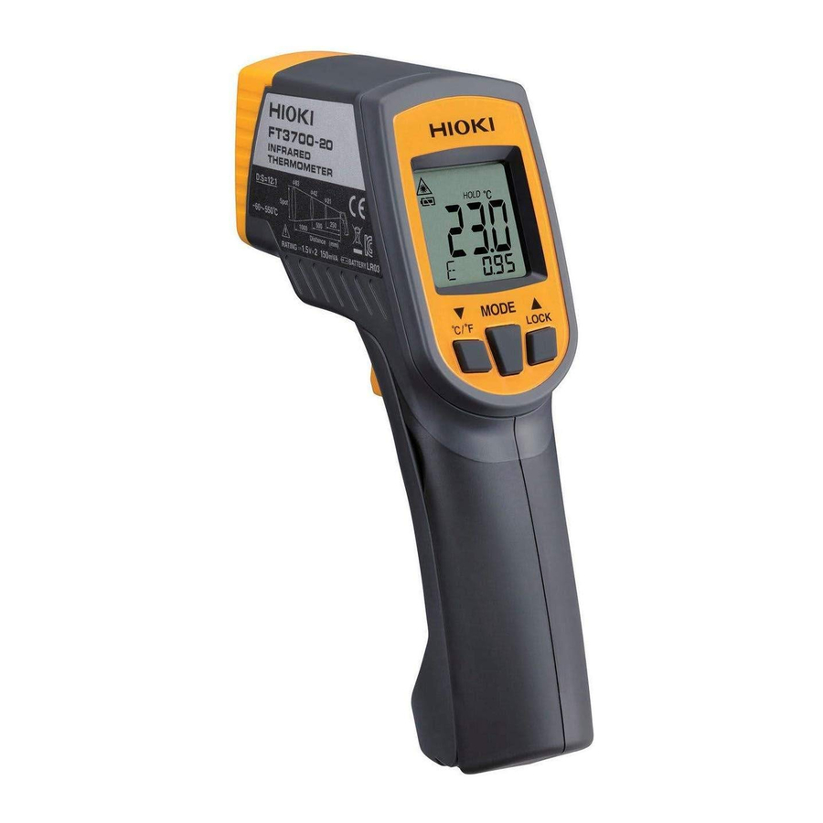
The Model FT3700-20, FT3701-20 is a non-contact thermometer using infrared rays.
It can measure the surface temperature of an object by measuring the energy level of the infrared rays emitted from the object without touching it.
- Liquid crystal display with backlight
- Two-point Laser marker beams
- Thermal emissivity setting function
- Display and sound alarm functions
Inspection and Maintenance
Initial Inspection
When you receive the instrument, inspect it carefully to ensure that no damage occurred during shipping. In particular, check the accessories, the liquid crystal display, the control keys, and the lens. If damage is evident, or if it fails to operate according to the specifications, contact your dealer or HIOKI representative.
Maintenance and Service
- To clean the instrument, wipe it gently with a soft cloth moistened withwater or mild detergent. Never use solvents such as benzene, alcohol, acetone, ether, ketones, thinners or gasoline, as they can deform and discolor the case.
- If the instrument seems to be malfunctioning, confirm that the batteries are not discharged before contacting your dealer or HIOKI representative.
- Pack the instrument so that it will not sustain damage during shipping, and include a description of existing damage. We do not take any responsibility for damage incurred during shipping.
Usage Notes
 Follow these precautions to ensure safe operation and to obtain the full benefits of the various functions.
Preliminary Checks
Before using the instrument the first time, verify that it operates normally to ensure that the no damage occurred during storage or shipping. If you find any damage, contact your dealer or HIOKI representative.

Do not allow the laser light beam to impinge upon any gas which can explode.

- Use of controls or adjustments or performance of procedures other than those specified herein may result in hazardous radiation exposure.
- The Model FT3700-20, FT3701-20 uses as a light source a semiconductor laser which emits visible light, and which conforms to IEC standard class 2 (IEC 60825-1). (Wavelength 640 nm to 660 nm, maximum power output 1 mW) Since there is considerable danger of this laser light causing damage to the eyes, be very careful not to direct this laser light into your eyes or those of another person.
- Do not look directly into the laser light from the optical system.
- When measuring the temperature of an object which has a mirror finish, be careful not to allow the laser light beam to be reflected off the surface into your eyes or those of another person.
- This instrument should be installed and operated indoors only, between 0 and 50°C and 80% RH or less.
- Do not store or use the instrument where it could be exposed to direct sunlight, high temperature or humidity, or condensation. Under such conditions, the instrument may be damaged and insulation may deteriorate so that it no longer meets specifications.
- This instrument is not designed to be entirely water- or dustproof. Do not use it in an especially dusty environment, nor where it might be splashed with liquid. This may cause damage.
- Do not use the instrument where it may be exposed to corrosive or combustible gases. The instrument may be damaged.
- Do not use the instrument near a source of strong electromagnetic radiation, or near a highly electrically charged object. These may cause a malfunction.
- To avoid damage to the instrument, protect it from physical shock when transporting and handling. Be especially careful to avoid physical shock from dropping.
- Do not point the lens at the sun or at any other source of strong light. If you do, the sensor may be damaged.
- Do not contact the lens against the object whose temperature is to be measured, or get it dirty, allow it to be scratched, or allow any foreign material to adhere to it. Doing so may cause errors.

The indicator  flashes when the remaining battery capacity is low. In this case, the instrument's reliability is not guaranteed. Replace the battery immediately.
Replacing Batteries
When replacing the batteries, be careful not to acciden tally pull the measuring trigger key. This may cause the laser marker to enter the eyes and is extremely dangerous. After replacing the batteries, be sure to close the cover before using the instrument.

- Battery may explode if mistreated. Do not short-circuit, recharge, disassemble or dispose of in fire.
- Handle and dispose of battery in accordance with local regulations.
- Do not mix old and new batteries, or different types of batteries. Also, be careful to observe battery polarity during installation. Otherwise, poor performance or damage from battery leakage could result.
- To avoid corrosion and damage to this instrument from battery leakage, remove the batteries from the instrument if it is to be stored for a long time.

- Hold the instrument with both hands as shown in the diagram.
- Twist the battery cover in the direction as shown in the diagram to open it.
- Take out the batteries.
- Install new batteries (LR03) in the case, being careful to observe proper battery polarity.
- Close the battery cover.
Remaining battery life indicator
 | There is ample battery life remaining. |
 | Replace the batteries soon. |
 | No battery life remaining. The instrument cannot be used in this state. |
The battery cover has been designed to fit tightly in order prevent accidental opening.
Names and Function of Parts

- LCD Display
- MODE Key
Changes the instrument's mode (see "Changing the Mode"). - Down/°C/ °F Key
Press one time: Changes (decreases) the setting.
Press and hold while pulling the measurement trigger (1 sec.):
Toggles the laser marker on and off.
Change temperature units (except when using the emissivity setting, HAL mode, or LAL mode). - Up/LOCK Key
Press one time: Changes (increases) the setting.
Turns continuous measurement mode on and off (except when using the emissivity setting, HAL mode, or LAL mode).
Press and hold while pulling the measurement trigger (1 sec.):
Toggles the backlight on and off. - Meas. Key
Pull the trigger to switch on the power to start measuring. - Infrared Lens
Infrared rays from the object whose temperature is to be measured are received here. - Laser
The laser marker beams are emitted from here. - Battery cover
LCD Display

- Indicates the lit setting for laser marker. (When this lamp is off, the laser maker beam is not emitted)
This lamp will blink when the laser marker beam is being emitted during lit setting. - Indicates the backlight setting. (When this lamp is off, the laser maker beam is not emitted)
- "HI" indicates that the alarm setting's upper limit temperature has been exceeded. "LO" indicates that the reading is lower than the lower limit temperature.
- Indicates that measurement is in progress.
- Indicates the battery consumption level (refer to Replacing Battery)
- Main display: Indicates the measurement value.
- Sub-display: Indicates the mode and associated value.
- Indicates the temperature units.
- Indicates that the measurement value is being maintained.
- Indicates that continuous measurement mode is active.
Measurement
Whenever the indication  is blinking, the laser marker beam is being emitted. Exercise extreme care not to allow the laser marker beam to enter your eyes or those of another person. Because of this laser light causing damage to the eyes.
- Consecutive measurements are carried out by pulling and holding themeasuring trigger key. Measurement will stop when the measuring trigger key is released and the last shown value will be retained.
- The instrument will automatically switch off approximately 15 secondsafter the measuring trigger key is released.
- Turning the Power On
With the power switch at OFF, pull the measuring trigger key to switch on the power to start measuring. - Thermal emissivity setting
- Press the MODE key to activate emissivity mode ("
![]() " will be shown on the display).
" will be shown on the display). - Press the
![]() keys to set thermal emissivity.
keys to set thermal emissivity. - Refer to the section on thermal emissivity for thermal emissivity setting.
- Press the MODE key to activate emissivity mode ("
- Measuring
Direct the lens toward the object whose temperature is to be measured.
 " will be shown on the display).
 keys to set thermal emissivity.
Measurement field of view

- The laser marker indicates the diameter of the measurement field ofview.
- The measurement field of view is defined as the measurement diameterin which the optical response is 90%. The object whose temperature is to be measured needs to be larger than the measurement diameter by an adequate margin. (1.5 to 2 times or more)
ON/OFF setting for laser marker
The laser marker is set to OFF in the factory default or immediately after replacing the batteries. To turn ON the laser marker, press and hold the  key (1 sec) while pulling the measuring trigger key. To turn OFF the laser marker is the same operation again.
Continuous measurement mode
Pressing the  /LOCK key while the instrument is on activates continuous measurement mode, except when using the emissivity setting, HAL mode, or LAL mode. This mode lets you take measurements continuously without needing to pull the measurement trigger.
- The instrument will turn off automatically about 60 minutes after continu-ous measurement mode is activated.
- When the laser marker is on, the sighting laser will only activate whenthe measurement trigger is pulled.
- Key response may be slow when continuous measurement mode is on.
Changing the Mode
Pressing the MODE key while the instrument is on causes it to cycle through the following modes:

MAX/MIN/DIF/AVG measurement
The instrument will display the maximum value, minimum value, difference between the maximum and minimum values, and average value since measurement began.
- Press the MODE key to display "MAX", "MIN", "dIF" or "AVG" on the subdisplay.
- The MAX/MIN/DIF/AVG value will be refreshed when you pull the mea-surement trigger or while continuous measurement mode is active.
- When using the continuous measurement mode, the key response maybe slow.
Alarm Function
The alarm can be set to go off whenever a value which is higher or lower than a threshold value inputted beforehand is reached. The alarm is in the form of a display and a buzzer.
- Pull the measuring trigger key to switch on the power.
- Press the MODE key to display "HAL" in the sub-display.
Press the![]() key to set the alarm setting's upper limit temperature.
key to set the alarm setting's upper limit temperature. - Press the MODE key to display "LAL" in the sub-display.
Press the![]() key to set the alarm setting's lower limit temperature.
key to set the alarm setting's lower limit temperature.
Error Indication
| Error Indication | Description | Remedy |
 | The change in ambient temperature is too great. | Allow the instrument to acclimate to the ambient temperature for about 30 minutes before use. |
 | The ambient temperature is outside the operating temperature range. | Use the instrument within the operating temperature range (0°C to 50°C). |
 | System error | Remove the battery, wait at least 1 minute, and then replace the battery. If you are unable to resolve the error, the instrument may be broken. Contact your dealer or HIOKI representative. |
 | The measurement value is outside the measurement range. | The measurement value cannot be displayed since it is outside the measurement range. |
Warning Labels
Location of labels used in the HIOKI "FT3700-20, FT3701-20 Infrared Thermometer" is as follows.

Specifications
Basic Specifications
| Function | Infrared temperature measurement |
| Additional Function | MAX, MIN, DIF (MAX-MIN), AVE measurement, Alarm function, Backlight function |
| Power supply | LR03 alkaline battery × 2 |
| Dimensions | Approx. 48 W × 172 H × 119 D mm (1.89"W × 6.77"H × 4.69"D) (excluding projections) |
| Mass | Approx. 256 g (9.0 oz.) (including LR03 alkaline battery × 2) |
| Location for use | Indoors, altitude up to 2000 m (6562-ft.) |
| Operating temperature and humidity | 0 to 50°C (32°F to 122°F), 80%RH or less (noncondensation) |
| Storage temperature and humidity | -10 to 50°C (14°F to 122°F), 80%RH or less (noncondensation) 50 to 60°C (122°F to 140°F), 70%RH or less (noncondensation) |
| Accessories | Instruction manual, LR03 alkaline battery × 2, Carrying case × 1 |
| Effect of radiated radio-frequency electromagnetic field | ±70°C at 3 V/m |
| Applicable standards | EMC: EN61326 Laser: IEC60825-1:1993+A1:1997+A2:2001 CLASS 2 LASER This product is complied with 21 CFR 1040.10 and 1040.11 except for deviations pursuant to Laser Notice No.50, dated June 24, 2007 |
Electrical characteristics
| Detection element | Thermopile |
| Temperature units | °C, °F |
| Measurement temperature range | FT3700-20: -60 to 550°C (-76 to 1022°F) FT3701-20: -60 to 760°C (-76 to 1400°F) |
| Display resolution | 0.1°C, 0.1°F (1°F at 1000°F and over) |
| Outside display of measurement range | FT3700-20: "Lo" mark lights when -60.0°C (-76.0°F) or less "Hi" mark lights when 550.0°C (1022°F) or higher FT3701-20: "Lo" mark lights when -60.0°C (-76.0°F) or less "Hi" mark lights when 760.0°C (1400°F) or higher |
| Response time | 1 second (90%) |
| Measurement wavelength | 8 to 14  m m |
| Thermal emissivity compensation | 0.10 to 1.00 by steps of 0.01 |
| Diameter of field of measurement | FT3700-20: 83 mm at 1000 mm (D:S=12:1) FT3701-20: 100 mm at 3000 mm (D:S=30:1) |
| Sighting | Two-point laser marker, 1 mW (MAX), Red (640 nm to 660 nm) It is illuminated in conjunction with pulling the measuring trigger key. |
| Battery low warning voltage | mark lights when 2.70 V (±0.1 V) or highermark lights when 2.70 V (±0.1 V) or lessmark flashes when 2.55 V (±0.1 V) or less, measurement value is fixed. Power turned off at 2.20 V (±0.1 V) |
| Rated supply voltage | 1.5 VDC × 2 |
| Maximum rated powers | 150 mVA |
| Continuous operating time | Approx. 140 hours (alkaline battery), When laser marker and backlight are OFF |
| Auto Power Off | Approx. 15 seconds |
Accuracy Specifications
| Accuracy (infrared) | -60.0 to -35.1°C (-76.0 to -31.1°F) Accuracy not specified -35.0 to -0.1°C (-31.0 to 31.9°F) ±10%rdg.±2°C (±(T-32)×0.1±4°F T=reading value(°F)) 0.0 to 100.0°C (-32.0 to 212.0°F) ±2°C 100.1 to 500.0°C (212.1 to 932.0°F) ±2%rdg 500.1to 550.0 (932.0 to 1022°F)(FT3700-20) 500.1to 760.0 (932.0 to 1400°F)(FT3701-20) Accuracy not specified (except when battery mark is blinking) |
| Guaranteed accuracy period | 1 year |
| Accuracy guarantee for temperature and humidity | 23°C ±3°C (73°F ±5°F), 80%RH or less (non-condensation) |
| Temperature coefficient | Measurement accuracy × 0.1/ °C |
Accuracy
rdg. :reading value (The value currently being measured and indicated on the measuring instrument)
Thermal Emissivity
This instrument allows thermal emissivity to be adjusted within the range of 0.10 to 1.00.Please refer to the following table when setting the thermal emissivity.
| Refractory & Building Materials | Metal | ||
| Alumina (coarse grain) | 0.45 | Aluminum (heavily oxidized) | 0.25 |
| Alumina (fine grain) | 0.25 | Aluminum Alloys various | 0.10 to 0.25 |
| Asbestos | 0.95 | Aluminum oxide at 260°C | 0.60 |
| Carbon (graphite) | 0.75 | Aluminum oxide at 800°C | 0.30 |
| Carbon (soot) | 0.95 | Brass (oxidized) | 0.60 |
| Carborundum(Trademark) | 0.85 | Brass (polished) | 0.10 |
| Concrete | 0.7 | Brass (roughened surface) | 0.20 |
| Fire clay | 0.75 | Cast iron (polished) | 0.20 |
| Marble | 0.90 | Cast iron (rough) rusted | 0.95 |
| Plaster | 0.90 | Cast iron (turned at 100°C) | 0.45 |
| Quartz (rough) | 0.90 | Cast iron (turned at 1000°C) | 0.60 to 0.70 |
| Red brick (rough) | 0.75 to 0.90 | Copper (oxidized) | 0.80 |
| Silica (coarse grain) | 0.55 | Copper (polished) | 0.05 |
| Silica (fine grain) | 0.40 | Iron plate(rusted) | 0.70 to 0.85 |
| Timber (various) | 0.80 to 0.90 | Lead (oxidized at 25°C) | 0.30 |
| Zirconium silicate at 850°C | 0.60 | Lead (oxidized at 200°C) | 0.60 |
| Zirconium silicate up to 500°C | 0.85 | Lead (pure) | 0.10 |
| Miscellaneous | Mild steel | 0.30 to 0.50 | |
| Aluminum lacquer | 0.50 | Molten cast iron | 0.30 |
| Enamel (any color) | 0.90 | Molten copper | 0.15 |
| Lacquer | 0.90 | Nichrome | 0.70 |
| Matte black paint | 0.95 to 0.98 | Nichrome (oxidized) | 0.95 |
| Oil paint (any color) | 0.95 | Nickel (pure) | 0.10 |
| Paper and cardboard | 0.90 | Nickel plate (oxidized) | 0.40 to 0.50 |
| Plastics | 0.80 to 0.95 | Polished aluminum | 0.10 |
| Plastics films (0.05 mm thick) | 0.50 to 0.95 | Rough ingot iron | 0.90 |
| Polythene film (0.03 mm thick) | 0.20 to 0.30 | Stainless steel (polished) | 0.10 |
| Rubber (rough) | 0.98 | Stainless steel (various) | 0.20 to 0.60 |
| Rubber (smooth) | 0.90 | Steel | 0.60 |
| Silicone polish | 0.70 | Steel plate (oxidized) | 0.90 |
| Water | 0.98 | ||
- Variations in the surface condition and color of the object whose temper-ature is to be measured may cause the thermal emissivity (
![]() ) to be somewhat different from the values in the above table. If an accurate temperature measurement is desired for an object whose thermal emissivity is not known, black body tape (commercially available) should be used. In this case the setting for thermal emissivity (
) to be somewhat different from the values in the above table. If an accurate temperature measurement is desired for an object whose thermal emissivity is not known, black body tape (commercially available) should be used. In this case the setting for thermal emissivity (![]() ) should be the value indicated on black body tape.
) should be the value indicated on black body tape. - Iron and other objects with low thermal emissivity reflect their surround-ing temperature, causing inaccuracies in measurement. The black body tape (commercially available) is also recommended when measuring these objects of low thermal emissivity.
- A black body is an object that represents a standard emissivity, and maynot necessarily be black in color.
 ) to be somewhat different from the values in the above table. If an accurate temperature measurement is desired for an object whose thermal emissivity is not known, black body tape (commercially available) should be used. In this case the setting for thermal emissivity (
Warranty
Warranty malfunctions occurring under conditions of normal use in conformity with the Instruction Manual and Product Precautionary Markings will be repaired free of charge. This warranty is valid for a period of one (1) year from the date of purchase. Please contact the distributor from which you purchased the product for further information on warranty provisions.
Headquarters
81 Koizumi, Ueda, Nagano 386-1192, Japan
TEL +81-268-28-0562
FAX +81-268-28-0568
E-mail: os-com@hioki.co.jp
URL http://www.hioki.com/
(International Sales and Marketing Department)
For regional contact information, please go to our website at http://www.hioki.com.
The Declaration of Conformity for instruments that comply to CE mark requirements may be downloaded from the HIOKI website.

Documents / Resources
References
Download manual
Here you can download full pdf version of manual, it may contain additional safety instructions, warranty information, FCC rules, etc.
Download Hioki FT3700-20, FT3701-20 - Infrared Thermometer Manual
Advertisement


Need help?
Do you have a question about the FT3700-20 and is the answer not in the manual?
Questions and answers