PowerDsine 3001 - 1-Port Power Over Ethernet Midspan Manual
- User manual (2 pages)
Advertisement
Notice
It is PowerDsine's policy to improve its products as new technology, components, software, and firmware become available. PowerDsine, therefore, reserves the right to change specifications without prior notice.
Trademarks
The product described in this guide is a licensed product of PowerDsine.
Technical Support
If you encounter problems when installing or using this product, please consult the PowerDsine website at: http://www.powerdsine.com
If these resources don't provide the help you need, please contact your local authorized PowerDsine reseller for additional technical support.
Safety Information
Important Safety Information
- Installation and removal of the PoE Midspan must be carried out by qualified personnel only.
- AC Power Cord Set:
- The power cord must have regulatory agency approval for the specific country in which it is used (i.e., UL, CSA, VDE, etc.).
- The power cord must be a three-conductor type (two current carrying conductors; one ground conductor) terminated on one end by an IEC 60320 appliance coupler (for connection to the PoE Midspan), and on the other end by a plug containing a ground (earthing) contact.
- The power cord must be rated for a minimum of 250Vac RMS operation, with a minimum rated current capacity of 5 amps (or a minimum wire 2 gauge of 18 AWG (0.75mm )). Note: PoE Midspan units installed in Australia require power cords with a minimum wire gauge of 16 AWG 2 (1.0 mm ).
- The AC wall socket-outlet must be near the PoE Midspan and easily accessible. You can remove AC power from the PoE Midspan by disconnecting the AC power cord from either the wall socket-outlet or the PoE Midspan appliance coupler.
The PoE Midspan data and data / power interfaces are qualified as SELV (Safety Extra-Low Voltage) circuits according to IEC 60950. These interfaces can only be connected to SELV interfaces on other equipment.

- Read the installation instructions before connecting the PoE Midspan to its power source.
- Follow basic electricity safety measures whenever connecting the PoE Midspan to its power source.
- This product relies on the building installation for shortcircuit (over current) protection. Ensure that a fuse or circuit breaker no larger than 120 VAC, 3A. U.S. (240 VAC, 1.5A international) is used on the phase conductor.
- A voltage mismatch can cause equipment damage and may pose a fire hazard. If the voltage indicated on the label is different from the power outlet voltage, do not connect the PoE Midspan to this power outlet.
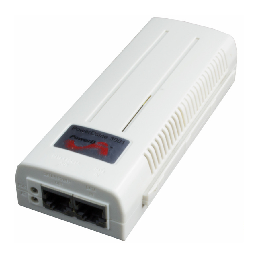
The PoE Midspan "Data In" and "Data & Power Out" ports are shielded RJ-45 data sockets. They cannot be used as Plain Old Telephone Service (POTS) telephone sockets. Only RJ-45 data connectors may be connected to these sockets.
Functions and Features
The device is design to meet the IEEE802.3af standard. The Power over Ethernet (PoE) Midspan adds 48VDC to unused (non-data) wires in standard Category 5 Ethernet cable. As a result, the PoE Midspan delivers both data and power to the terminal.
EMC Compliance: Category 5 foiled twisted-pair cables must be used to ensure compliance with requirements of FCC Part 15, subpart B, Class B. The use of unshielded cables (Category 5 for 10BASE-T ports or for 100BASE-Tx ports) complies with Class A requirements.
Preliminary Steps
- Ensure AC power is applied to the PoE Midspan, using an operational AC cable with an appropriate ground connection.
- Ensure that output Ethernet cable is connected to the Data & Power Out port.
- Verify that power ready Ethernet compatible device is connected.
Do not use cross over cable between the PoE Midspan output port and the load device!
Installation
The PoE Midspan may be or wall/bench mounted using the rear side holes.
 NOTES: Before mounting the PoE Midspan to a fixed location:
- Do not to cover the PoE Midspan or block the airflow to the PoE with any foreign objects. Keep the PoE Midspan away from excessive heat and humidity, and free from vibration and dust.
- Ensure that the cable length from the Ethernet network source to the terminal does not exceed 100 meters (333 Feet). The PoE is not a repeater and does not amplify the Ethernet data signal.
- Use a splitter if desired; ensure that the splitter is connected close to the terminal and not on the Midspan!
- No "on-off" switch exists; Simply plug the PoE Midspan into an AC power source.
Installing the Unit

Figure 1: connecting the PoE Midspan
- Connect the PoE Midspan to an AC outlet (100-240 VAC), using a standard power cord.
- Connect the unit Data In jack (input) to the remote Ethernet network switch Patch panel and the Data & Power Out jack (output) to the terminal.
Indicators
| LED | AC (Main) | Port |
| Green | Indicates that the power is on (Power is active) | indicates that a remote terminal is connected |
| Green Blinking | Output voltage is out of range | Overload or short circuit |
Specifications
Environmental Specifications
| Mode | Temperature | Humidity |
| Operating | 0 to 40°C 32 to 104°F | 10 to 90% (no condensation allowed) |
| Storage | -20 to 70°C -4 to 158°F | 10 to 90% (no condensation allowed) |
Electrical Specifications
| Input Voltage | 90 to 264 VAC (47-63 Hz) |
| Input Current (110 - 220VAC) | 0.5 ampere (max) |
| Minimum Available Output Power | 15.4 Watts |
| Nominal Output Voltage | 45 to 56 VDC |
Ethernet Interface
| Input (Data In): Ethernet 10/100Base-T | RJ 45 female socket |
| Output (Data & Power Out): Ethernet 10/100Base-T, plus 48 VDC | RJ 45 female socket, with DC voltage on wire pairs 7-8 and 4-5. |
Troubleshooting
| Symptom | Corrective Steps |
| Midspan does not power up |
|
| A port indicator is not lit and the PD does not operate |
|
| The end device operates, but there is no data link |
|

Documents / Resources
References
Download manual
Here you can download full pdf version of manual, it may contain additional safety instructions, warranty information, FCC rules, etc.
Download PowerDsine 3001 - 1-Port Power Over Ethernet Midspan Manual
Advertisement

Need help?
Do you have a question about the 3001 and is the answer not in the manual?
Questions and answers