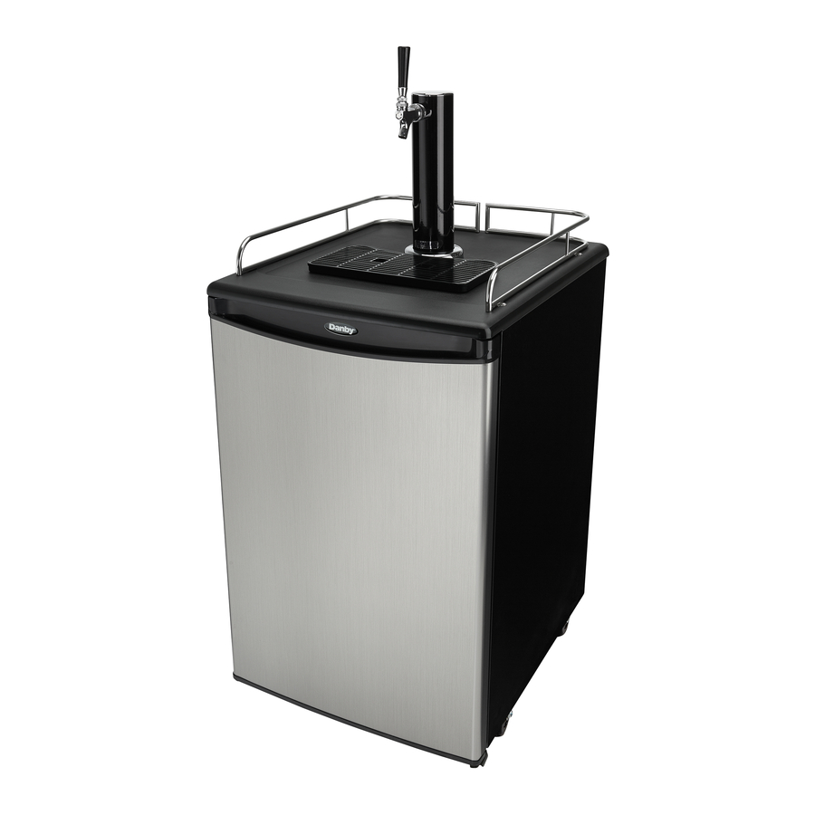
Danby DKC054A1BSLDB - 5.4 cu. ft. Single Tap Keg Cooler Manual
- Owner's manual (45 pages) ,
- Owner's use and care manual (20 pages)
Advertisement
Overview

- Pressure gauge dial
- Pressure relief ring
- Open / Close valve
- Tank strap
Ensure the CO2 tank is empty before courier or 3rd party transport.

A full or partially full CO2 tank is under extreme pressure. Uncontrolled release of pressure is extremely dangerous. The instructions below use the regulator to control the release of this pressure in a safe manner. Do not bypass the regulator.
- Ensure tank is secure
- Fully open valve by turning counter-clockwise. Pressure gauge dial will show a value if tank contains pressure.
- Gently pull pressure relief ring. Released gas should be heard.
- The pressure dial will read zero when the tank is empty. Continue to hold pressure relief open until tank is empty.
- Release the pressure relief ring.
- Fully close valve by turning clock-wise.
Welcome
We are proud of our quality products and we believe in dependable service. We suggest that you read this owner's manual before plugging in your new appliance as it contains important operation information, safety information, troubleshooting and maintenance tips to ensure the reliability and longevity of your appliance.
Visit www.Danby.com to access self service tools, FAQs and much more. For additional assistance call 1-800-263-2629.
Note the information below; you will need this information to obtain service under warranty.
You must provide the original purchase receipt to validate your warranty and receive service.
Model Number:
Serial Number:
Date of Purchase:
Need Help?
Before you call for service, here are a few things you can do to help us serve you better.
Read this owner's manual:
It contains instructions to help you use and maintain your appliance properly.
If you receive a damaged appliance:
Immediately contact the retailer or builder that sold you the appliance.
Save time and money:
Check the troubleshooting section at the end of this manual before calling. This section will help you solve common problems that may occur.

Important Safety Information
 READ AND FOLLOW ALL SAFETY INSTRUCTIONS
SAFETY REQUIREMENTS
Risk of fire or explosion. Flammable refrigerant used. Do not puncture refrigerant tubing.
- Do not use mechanical devices to defrost refrigerator.
- Ensure that servicing is done by factory authorized service personnel, to minimize product damage or safety issues.
- Consult repair manual or owner's guide before attempting to service this product. All safety precautions must be followed.
- Dispose of properly in accordance with federal or local regulations.
- Follow handling instructions carefully.

Keep ventilation openings, in the appliance enclosure or in the built-in structure, clear of obstruction.
Do not use mechanical devices or other means to accelerate the defrosting process, other than those recommended by the manufacturer.
Do not damage the refrigerant circuit.

Do not use electrical appliances inside the food storage compartments of the appliance, unless they are of the type recommended by the manufacturer.

Children should be supervised to ensure that they do not play with the appliance.
Risk of child entrapment. Before throwing away an old appliance:
- Remove the door or lid.
- Leave shelves in place so that children may not easily climb inside.
This appliance is intended to be used in household and similar applications such as:
- Staff kitchen areas in shops, offices and other working environments;
- Farm houses and by clients in hotels, motels and other residential type environments;
- Bed and breakfast type environments;
- Catering and similar non-retail applications.
SAFETY REQUIREMENTS
This appliance is not intended for use by persons (including children) whose physical, sensory or mental capabilities may be different or reduced, or who lack experience or knowledge, unless such persons receive supervision or training to operate the appliance by a person responsible for their safety.
Do not store explosive substances such as aerosol cans with a flammable propellant in this appliance.
GROUNDING INSTRUCTIONS
This appliance must be grounded. Grounding reduces the risk of electrical shock by providing an escape wire for the electrical current.
This appliance has a cord that has a grounding wire with a 3-prong plug. The power cord must be plugged into an outlet that is properly grounded. If the outlet is a 2-prong wall outlet, it must be replaced with a properly grounded 3-prong wall outlet. The serial rating plate indicates the voltage and frequency the appliance is designed for.
Improper use of the grounding plug can result in a risk of electric shock. Consult a qualified electrician or service agent if the grounding instructions are not completely understood, or if doubt exists as to whether the appliance is properly grounded.
Do not connect your appliance to extension cords or together with another appliance in the same wall outlet. Do not splice the power cord. Do not under any circumstances cut or remove the third ground prong from the power cord. Do not use extension cords or ungrounded (two prongs) adapters.
If the power supply cord is damaged, it must be replaced by the manufacturer, its service agent or similar qualified person in order to avoid hazard.
SAVE THESE INSTRUCTIONS!
CO2 CAN BE DANGEROUS!
CO2 Cylinders, when charged, contain high pressure compressed gas which can be hazardous if not handled properly. Read and understand the following procedures for CO2 cylinders before installation:
- Always check the D.O.T. (Department of Transportation) as well as the T.C. (Transport Canada) test date located on the neck of the cylinder before installation. If the date is older than fi ve (5) years, do not use! Return the gas cylinder to a gas supplier for recertification (service charges may be applicable).
- Always connect a CO2 gas cylinder to a regulator. Failure to do so could result in an explosion which can possibly result in death or injury when the cylinder valve is opened.
- Always follow correct procedures when cylinders are changed as per local codes.
- Always secure a CO2 gas cylinder in an "upright" position.
- Always keep a CO2 gas cylinder away from heat. Store extra cylinders in a cool place (preferably 70°F/21°C). Securely fasten with a chain in an upright position when storing.
- Always ventilate and leave the area immediately after any leakage of CO2.
- Never connect a CO2 gas cylinder directly to a beer keg.
- Never drop or throw a CO2 cylinder.
- Never connect a keg without at least one safety pressure release. There are two safety mechanisms in the pressure system;
- One at or on the CO2 regulator
- One at or on the product container coupler in the pressure gas line.
Note: The regulator and keg coupler supplied with this appliance are inclusive of such safety mechanisms.
CO2 CAN BE DANGEROUS!
If it becomes difficult to breathe and/or your head starts to ache, abnormal concentrations of carbon dioxide (CO2) may be present in the area.
CLOSE THE MAIN VALVE ON THE CO2 CYLINDER, VENTILATE AND LEAVE THE ROOM IMMEDIATELY!
Beer is easily available with Danby's Keg Cooler, however, it is not intended to be available to people under the legal age to consume beer. Danby does not assume liability for the unlawful use or consumption of the beer.
PLEASE DRINK RESPONSIBLY AND PLEASE DON'T DRINK AND DRIVE!
CO2 GAS CAN BE DANGEROUS
CO2 cylinders contain high-pressure compressed gas which can be hazardous if not handled properly. Make sure to read and understand all safety procedures for CO2 cylinders before installation.
SAVE THESE INSTRUCTIONS!
INSTALLATION INSTRUCTIONS
FEATURES

- Beer Tower
- Rubber Gasket (may not be required in all configurations)
- Guard Rail
- Drip Tray
- Thermostat dial
- Keg Coupler
- Beer Keg (not included)
- Metal Support Plate
- Casters
- CO2 Regulator
- CO2 Tank
- CO2 Tank Support
BEFORE USING YOUR KEG COOLER
- Remove the exterior and interior packaging.
- Check to be sure you have all the following parts:
- 2 guard rails
- 1 drip tray (2 pieces)
- 1 CO2 tank support
- 1 CO 2 regulator
- 1 CO2 tank (empty)
- 1 CO 2 gas line hose (coloured)
- 1 beer hose
- 1 beer keg coupler
- 1 beer tower
- 1 faucet handle
- 1 metal plate for cabinet bottom
- 3 wire shelves
- 1 steel clamp for coloured hose
- 2 plastic washers for front casters
- 4 casters (2 front with locks)
Note: This appliance includes an American Sankey tap coupler only.
Note: This keg cooler accepts domestic kegs up to 16-1/8" in diameter and up to 23-3/8" in height. Check with the distributor to make sure the keg is correct size.
INSTALLATION LOCATION
- Place the appliance on a floor that is strong enough to support it when it is fully loaded.
- Do not place the appliance in direct sunlight or near sources of heat, such as a stove or heater, as this can increase electrical consumption. Extreme cold ambient temperatures may also cause the appliance to perform improperly.
- Do not use the appliance near water, for example in a wet basement or near a sink.
- This appliance is intended for indoor use only. It is not designed for outside installation, including anywhere that is not temperature controlled (garages, porches, vehicles, etc.).
- Before connecting the appliance to a power source, let it stand upright for approximately 6 hours. This will reduce the possibility of a malfunction in the cooling system from handling during transportation.
- This appliance is intended for free-standing installation only and is not intended to be built into a cabinet or counter. Building in this appliance can cause it to malfunction.
INSTALLATION DIAGRAM

- CO2 regulator
- CO2 gas tank
- Coloured CO2 hose
- Faucet assembly
- Tower
- Clear hose
- Coupler
- Keg
CASTER INSTALLATION INSTRUCTIONS

Install the four casters. The two locking casters should be placed at the front. Four screw holes have been pre-drilled into the bottom of the cabinet at each corner for each caster. Put the plastic washers provided on the front casters before installing them.
CASTOR BRAKES
The two front casters are supplied with brakes to ensure the appliance does not move excessively while being used. It is recommended to engage the brakes while the appliance is in use to avoid damage to the appliance, the contents or personal property.

INSTALLATION OF CO2 TANK SUPPORT

Install the metal support onto the four studs located on the exterior back wall of the cabinet.
Align the holes in the support with the studs and push down firmly.
INSTALLATION OF CO2 TANK AND CO2 REGULATOR

The CO2 tank does not come filled. The tank must be filled with CO2 before use.
Place the charged tank into the support stand.
Attach the CO2 regulator to the tank by turning the regulator nut onto the tank valve, making sure the washer is securely inserted into the connecting nut. Tighten snug using an adjustable wrench (not supplied) and ensure there are no leaks, i.e. no hissing sounds when the CO2 is turned on.
INSTALLATION OF CO2 AIR LINE AND CONNECTION TO CO2 REGULATOR

Remove the plug located at the exterior back of the cabinet, in the top left hand corner. Save the plug for later use to convert the appliance to a refrigerator.
Feed the gas line through the cabinet and out through the uncovered hole.
Attach the open end of the hose to the hose barb connection on the regulator. Secure the hose by using one clamp provided. Use pliers or a screwdriver to tighten the clamp to prevent leaks.
INSTALLATION OF THE BEER TOWER
- Remove the plug from the top of the fridge cabinet by twisting and pulling out. Save the plug for later use to convert the appliance to a refrigerator.
- Unravel the beer line (clear hose) from the tower and insert the beer line and wing nut through the uncovered hole on top of the cabinet.
- Secure the beer tower assembly to the top of the cabinet by pressing down and turning the tower to lock in place. Ensure the faucet is aligned with the front of the appliance.
- The rubber gasket can be used to make the connection between the tower and the cooler tighter if needed. If the beer tower will not turn to lock in place, try removing the rubber gasket. The rubber gasket may not be required in all configurations.
Note: If the faucet is leaking or if the beer is very foamy, ensure that the washers inside the faucet are intact. Replace the washers with spare parts from the accessory bag, if necessary.

- Handle washer
- Tap washer
- Spout washer
FAUCET WRENCH
The provided faucet wrench is for either removing or tightening the faucet connection. If the beer is not flowing freely, use the wrench to remove the faucet for cleaning. If the faucet connection is leaking, use the wrench to tighten the faucet connection.
PLASTIC FAUCET HANDLE
Attach the black plastic handle to the top of the faucet. Hold the silver nut underneath so it does not turn. If there is a small drip from the faucet, the silver nut may be overtightened. Unscrew silver nut counterclockwise by one turn.
INSTALLATION OF THE PROTECTIVE METAL PLATE
The protective metal plate should be installed on the bottom of the inside of the cabinet. This plate should always be installed when a keg is in place to protect the floor of the cabinet from damage.
INSTALLATION OF THE BEER KEG
- Two people should lift the keg to avoid back injury
- Position the keg directly in front of the open door.
- Using the keg handles, lift the front of the keg just enough so the front end is resting on the front edge of the keg cooler bottom cabinet.
- Grasp the keg handles and slide it all the way into the cabinet.
INSTALLATION OF THE CO2 AIR LINE HOSE
Attach the end of the coloured air line hose to the hose connection on the side of the coupler. Ensure that the reed valve is inserted into the connection, number 4 on the image below.
If, after assembly, beer will not flow, ensure that the reed valve has a small hole in it. If there is no hole in the reed valve then CO2 cannot enter the line and the beer will not flow.
CONNECTING THE BEER TOWER TO THE COUPLER
- Ensure all washers are properly inserted into the coupler, as per the below image.
- Ensure the check valve is in place inside the coupler, number 2 on the below image.
- Place the wing nut attached to the end of the beer line into the top of the coupler, turning until tight.
If, after assembly, the beer is very foamy, it most likely means that a connection in the coupler is leaking and air is entering the lines. Double check all connections in the coupler and replace the washers from the accessory bag as necessary.

- Valve washer
- Check valve
- O-type washer
- Reed valve
- Valve washer
- Valve washer
INSTALLATION OF THE KEG COUPLER
Insert the keg coupler into the locking neck of the beer keg and turn it clockwise to lock into position, making sure the keg coupler handle is in the closed position, with the handle up.

- Coupler pressure release valve
- Handle in closed position
OPERATING INSTRUCTIONS
HOW TO TAP A KEG OF BEER
- Make sure the CO2 is turned off and the valve on the regulator is in the closed position.
- Pull out and release the pressure release valve on the coupler to purge any air pressure.
- Make sure the faucet handle is in the closed position.
- Pull the coupler handle out and downward until it locks into its open position. The teeth on the underside of the coupler will bite into the locking neck of the beer keg.
Note: If a keg is very tall, it may be necessary to connect the coupler to the keg before inserting the keg into the keg cooler.

- Coupler pressure release valve
- Handle in open position
OPENING THE CO2 TANK MAIN VALVE
- Make sure the secondary shut-off valve (shown below in "open" position) is closed. To open the main CO2 cylinder valve, slowly turn the main valve counter-clockwise until fully open.
- Notice the needle on the regulator gauge start to climb.
ADJUSTING THE CO2 REGULATOR
The gauge monitors internal keg pressure and should be adjusted to read between 8-12 PSI. The pressure can be adjusted as needed. After making any adjustment to the PSI, wait 5 - 10 minutes before attempting to pour another beer to allow the pressure to equalize.
- If the beer is very foamy, try turning the pressure down.
- If the flow of beer is very weak, try turning the pressure up.
- Loosen the lock nut.
- Turn the adjustment screw with a fl at screwdriver.
- To increase pressure, turn screw clockwise.
- To decrease pressure, turn screw counter-clockwise.
- Allow several minutes for the keg to properly pressurize before adjusting the pressure further. The regulator gauge may drop while this happens.
- Retighten the lock nut to ensure the pressure does not get adjusted accidentally.
Note: Listen for hissing along all connections to identify if there are any leaks.

- Connection to C02 tank
- Shut off valve (open position)
- Lock nut
- Adjustment screw
DISPENSING OF BEER
- Keep beer keg refrigerated at all times.
- Never allow beer lines to dry out.
- Use clean glassware before pouring.
- Hold glass at a 45° angle, when it is 2/3 full, start to straighten glass as the glass fi lls.
- Always make sure the faucet handle is pushed all the way back.
Note: The refrigerator compartment cannot accommodate the "Coors" style beveled barrel keg.
Note: Our keg cooler accepts domestic kegs up to 16-1/8" in diameter and up to 23-3/8" in height. Check with your distributor to make sure keg is correct size.
Note: It is important to allow the keg to sit upright and undisturbed, for 2 hours before tapping.
SETTING THE TEMPERATURE
The temperature is controlled by adjusting the thermostat control knob.
- The thinnest part of the dial is the warmest setting.
- The thickest part of the dial is the coldest setting.
- To turn off the cooling, rotate the control knob to the "0" (OFF) position.
![]()

AUTOMATIC DEFROSTING
There is no need to defrost the keg cooler. Defrost water collects and passes through the drain outlet in the rear wall into a tray located above the compressor, where it evaporates.
Note: If the appliance is unplugged, power lost or turned off, wait 3 to 5 minutes before restarting the appliance. If there is an attempt to restart before this time delay, the compressor may not start.
CONVERTING TO A REFRIGERATOR
- Turn the thermostat dial to the "OFF" position.
- Close the main valve on the CO2 cylinder.
- Close the secondary shut-off valve on the regulator pipe.
- Close the connection between the beer keg and the keg coupler.
- Drain any remaining beer from the lines. (We recommend cleaning at this point, please see Care and Maintenance section).
- Disconnect the beer line and CO2 gas line from the keg coupler.
- Remove the beer keg.
- Remove the keg coupler.
- Disconnect the gas line from the CO2 cylinder.
- Remove the CO2 gas line from cabinet plug.
- Replace the gas line rear cabinet plug.
- Remove the beer tower. Also pull the beer line through the top of the cabinet.
- Replace the top cabinet plug.
- Adjust the temperature as desired.
Note: In order to convert the appliance, the gas line must be disconnected from the regulator in order to remove it from the cabinet.
Note: Install the shelf by sliding it into the desired spot in the appliance.
DOOR REVERSAL INSTRUCTIONS
If the appliance is placed on its back or side for any length of time during this process, it must be allowed to remain upright for 6 hours before plugging it in to avoid damage to internal components.
- Remove the lower hinge from the bottom right side of the cabinet. Remove the door from the cabinet.

- Remove the hinge pin from the upper right side of the cabinet. Install it on the upper left side of the cabinet.

- Install the door on the cabinet and install the lower hinge on the bottom right side of the cabinet.
Note: Ensure the top of the door is level with the top of the cabinet and that the rubber gasket is making a good seal with the cabinet all the way around before tightening the screws.


CARE & MAINTENANCE
CLEANING THE KEG COOLER
- Turn the temperature control to "OFF", unplug the keg cooler, and remove the contents.
- Wash the inside surfaces with a warm water and baking soda solution. The solution should be 2 tablespoons of baking soda to a quart of water.
- Wash the shelves and stand with a mild detergent solution.
- Wipe down any electrical controls with a dry cloth.
- Wash the outside cabinet with warm water and mild liquid detergent. Rinse well and wipe dry with a clean soft cloth.
CLEANING THE BEER LINES
Beer lines have to periodically be cleaned because of a crystallized sugar build up which forms on the fittings, lines and taps. If the build up is not completely removed in a cleaning process it will leave an unsanitary surface that can harbor microorganisms which will cause an undesirable flavour and/or cause the beer to go fl at. Sufficient build up will also lead to dispensing problems ranging from foamy beer to fl at beer, regardless of the carbonation levels or the quality or age of the beer in the keg.
Scheduled line and faucet cleaning eliminates the build-up, protecting the integrity of the product and condition of the dispensing system and seals. The beer line should be cleaned and rinsed with hot water approximately once every three weeks or every other keg - which ever comes first. The faucet should be cleaned with hot water on a weekly basis or prior to every use if not used on a regular basis.
Note: If the faucet handle becomes stuck or hard to move, this is usually indicative that it requires cleaning. DO NOT apply force to move the handle in this situation, as this can lead to damaging the handle or faucet and will not be covered by the warranty.
TROUBLESHOOTING
Danby Consumer Care: 1-800-263-2629
Hours of operation: Monday to Thursday 8:30 am - 6:00 pm
Eastern Standard Time Friday 8:30 am - 4:00 pm Eastern Standard Time
Information in this manual is subject to change without notice.
| PROBLEM | POSSIBLE CAUSE |
The unit does not operate |
|
Turns on and off frequently |
|
Vibrations |
|
| The keg cooler seems to make too much noise |
|
The door will not close properly |
|
Excessive beer foam |
|
Weak beer flow |
|
www.Danby.com;

DANBY PRODUCTS LIMITED, ONTARIO, CANADA N1H 6Z9
DANBY PRODUCTS INC., FINDLAY, OHIO, USA 45840

Documents / Resources
References
Download manual
Here you can download full pdf version of manual, it may contain additional safety instructions, warranty information, FCC rules, etc.
Download Danby DKC054A1BSLDB - 5.4 cu. ft. Single Tap Keg Cooler Manual
Advertisement


Need help?
Do you have a question about the DKC054A1BSLDB and is the answer not in the manual?
Questions and answers