Advertisement
DESCRIPTION
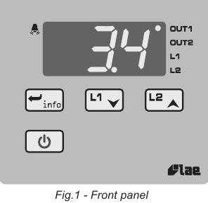
INDICATION
 | Channel 1 output |
 | Channel 2 output |
 | Channel 1 setpoint modification |
 | Channel 2 setpoint modification |
 | Alarm |
 | Info / Enter button |
 | Increase / Modify Setpoint 2 button |
 | Modify Setpoint 1 / Decrease button |
 | Exit / Stand-by button |
INSTALLATION
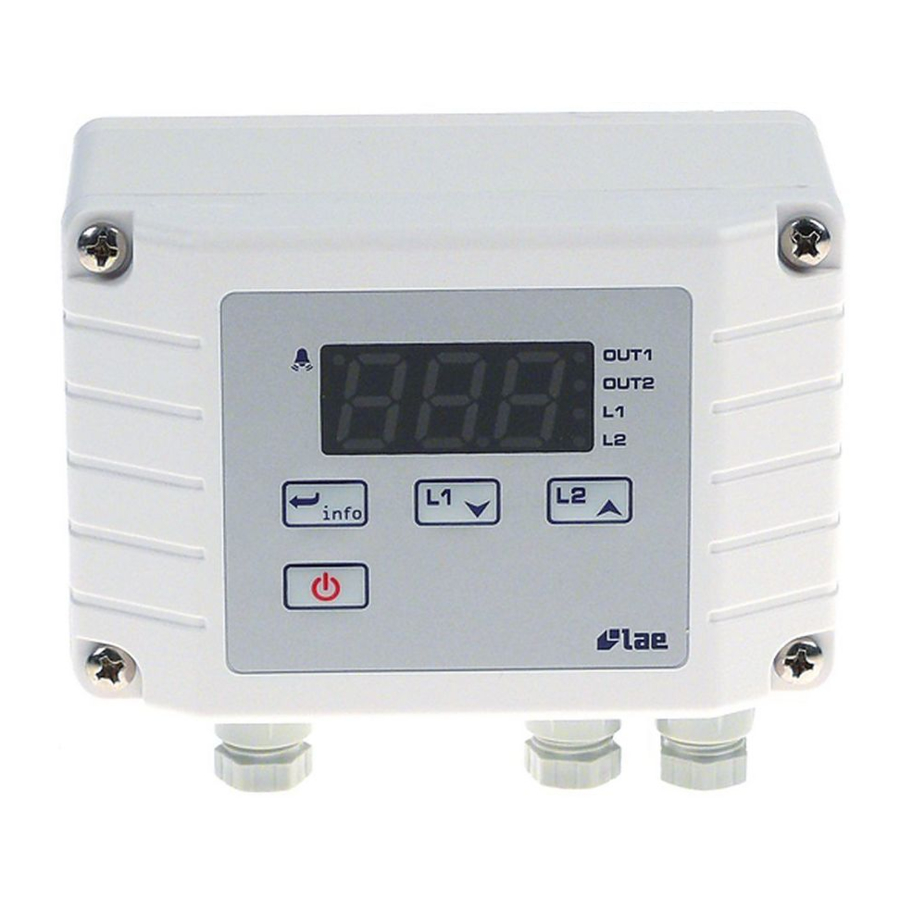
- The AC1-2W sizes 110x75x55 mm (WxHxD). Fix the plate to the panel using 2 cheese-headed screws with 4 or 5 mm diameter and then apply the instrument casing to the plate. This should be done for vertical panels and for correct positioning of the instrument with the outlets at the bottom.
- Make sure that electrical connections comply with the paragraph "wiring diagrams". To reduce the effects of electromagnetic disturbance, keep the sensor and signal cables well separate from the power wires.
- Place the probe T1 inside the room in a point that truly represents the temperature of the stored product.
OPERATION
DISPLAY
During normal operation, the display shows either the temperature measured or one of the following indications:
 | Controller in stand-by |
 | Probe T1 overrange or failure |
 | Room high temperature alarm |
 | Room low temperature alarm |
 | Controller in autotuning |
 | In tuning: timeout1 error |
 | In tuning: timeout2 error |
 | In tuning: overrange error |
MENU INFO
The information available in this menu is:
 | Maximum temperature recorded |
 | Minimum temperature recorded |
 | Keypad state lock |
Access to menu and information displayed.
- Press and immediately release button
![]() .
. - With button
![]() or
or ![]() select the data to be displayed.
select the data to be displayed. - Press button
![]() to display value.
to display value. - To exit from the menu, press button
![]() or wait for 10 seconds.
or wait for 10 seconds.
Reset of THI, TLO recordings- With button
![]() or
or ![]() select the data to be reset.
select the data to be reset. - Display the value with button
![]() .
. - While keeping button
![]() pressed, use button
pressed, use button ![]() .
.
- With button
CHANNEL 1 SETPOINT
Display and modification of desired temperature value
- Press and release button
![]() : the LED L1 blinks, the display shows 1SP for 1 second and then the setpoint associated value.
: the LED L1 blinks, the display shows 1SP for 1 second and then the setpoint associated value. - Press buttons
![]() or
or ![]() to set the desired value (adjustment is within the minimum SPL and maximum SPH limit).
to set the desired value (adjustment is within the minimum SPL and maximum SPH limit). - To store the new value press button
![]() , or wait for 10 seconds.
, or wait for 10 seconds. - To go back to normal mode without saving the new value, press
![]() .
.
 : the LED L1 blinks, the display shows 1SP for 1 second and then the setpoint associated value.
 , or wait for 10 seconds.
CHANNEL 2 SETPOINT
- With the auxiliary output set as thermostat control ( OAU=THR), it's possible to modify setpoint 2 during the normal operation of the controller.
- Press and release button
![]() : the LED L2 blinks, the display shows 2SP for 1 second if setpoint 2 is an absolute threshold (2SM = ABS), alternatively the display shows 2DF, if setpoint 2 is a threshold relative to setpoint 1 (2SM = REL), then the value associated to the parameter appears.
: the LED L2 blinks, the display shows 2SP for 1 second if setpoint 2 is an absolute threshold (2SM = ABS), alternatively the display shows 2DF, if setpoint 2 is a threshold relative to setpoint 1 (2SM = REL), then the value associated to the parameter appears. - Press buttons
![]() or
or ![]() to set the desired value.
to set the desired value. - To store the new value press button
![]() or wait for 10 seconds.
or wait for 10 seconds. - To go back to normal mode without saving the new value, press
![]() .
.
 : the LED L2 blinks, the display shows 2SP for 1 second if setpoint 2 is an absolute threshold
 STAND-BY
Button  , when pressed for 3 seconds, allows the controller to be put on a standby or output control to be resumed (with SB = YES only).
KEYPAD LOCK
The keypad lock avoids undesired, potentially dangerous operations, which might be attempted when the controllers is operating in a public place. In the INFO menu, set parameter LOC = YES to inhibit all functions of the buttons. To resume normal operation of keypad, adjust setting so that LOC = NO.
CONTROLLER AUTOTUNING IN PID MODE
Before starting
In the setup mode (see configuration parameters): set 1CM = PID; make sure that 1CH matches the desired operation mode (1CH = REF for refrigerating control, 1CH = HEA for heating control); then adjust setpoint 1SP at the desired value.
Start autotuning
During normal operation, keep buttons  +
+  pressed for 3 seconds. 1CT blinks on the display. With + or
  set the cycle time in order to define the dynamic of the process to be controlled. To abort the autotuning function, press ; to start autotuning press + or wait for 30 seconds.
During autotuning
During the entire autotuning phase, the display alternates TUN with the actual temperature measured. In case of power failure, when power is resumed, after the initial autotest phase, the controller resumes the autotuning function. To abort the autotuning, without modifying the previous control parameters, keep button pressed for 3 seconds. After the autotuning has taken place successfully, the controller updates the control parameters and start to control.
Errors
If the autotuning function failed, the display shows an error code:
- E1 timeout1 error: the controller could not bring the temperature within the proportional band. Increase 1SP in case of heating control, vice versa, decrease 1SP in case of refrigerating control and re-start the process.
- E2 timeout2 error: the autotuning has not ended within the maximum time allowed (1000 cycle times). Re-start the autotuning process and set a longer cycle time 1CT.
- E3 temperature overrange: check that the error was not caused by a probe malfunction, then decrease 1SP in case of heating control, vice versa increase 1SP in case of refrigerating control and then re-start the process.
- To eliminate the error indication and return to the normal mode, press button
![]() .
.
Control improvement
- To reduce overshoot, reduce the integral action reset 1AR
- To increase the response speed of the system, reduce the proportional band 1PB. Caution: doing this makes the system less stable.
- To reduce swings in steady-state temperature, increase the integral action time 1IT; system stability is thus increased, although its response speed is decreased.
- To increase the speed of response to the variations in temperature, increase the derivative action time 1DT. Caution: a high value makes the system sensitive to small variations and it may be a source of instability.
RECALIBRATION
- Have a precision reference thermometer or a calibrator to hand. Ensure that OS1 = 0 and SIM = 0.
- Switch the controller off then on again.
- During the auto-test phase, press buttons
![]() +
+ ![]() and keep them pressed till the controller shows 0AD.
and keep them pressed till the controller shows 0AD. - With buttons
![]() and
and ![]() select 0AD or SAD: 0AD allows a calibration of 0, inserting a constant correction over the whole scale of measurement. SAD allows a calibration of the top part of the measurement scale with a proportional correction between the calibration point and 0.
select 0AD or SAD: 0AD allows a calibration of 0, inserting a constant correction over the whole scale of measurement. SAD allows a calibration of the top part of the measurement scale with a proportional correction between the calibration point and 0. - Press
![]() to display the value and then use
to display the value and then use ![]() +
+ ![]() or
or ![]() to make the read value coincide with the value measured by the reference instrument.
to make the read value coincide with the value measured by the reference instrument. - Exit from calibration by pressing button
![]() .
.
CONFIGURATION PARAMETERS
- To get access to the parameter configuration menu, press button
![]() +
+ ![]() for 5 seconds.
for 5 seconds. - With button
![]() or
or ![]() select the parameter to be modified.
select the parameter to be modified. - Press button
![]() to display the value.
to display the value. - By keeping button
![]() pressed, use button
pressed, use button ![]() or
or ![]() to set the desired value.
to set the desired value. - When button
![]() is released, the newly programmed value is stored and the following parameter is displayed.
is released, the newly programmed value is stored and the following parameter is displayed. - To exit from the setup, press button
![]() or wait for 30 seconds.
or wait for 30 seconds.
| PAR | RANGE | DESCRIPTION | ||||
| SCL | 1°C; 2°C; °F | Readout scale (see table of input specifications) upon changing the SCL value, it is then absolutely necessary to reconfigure the parameters relevant to the absolute and relative temperatures (SPL, SPH, 1SP, 1HY etc..) | ||||
| SPL | -50°...SPH | Minimum limit for 1SP setting | ||||
| SPH | SPL...150° | Maximum limit for 1SP setting. | ||||
| 1SP | SPL... SPH | Setpoint (value to be maintained in the room). | ||||
| 1CM | HY; PID | Control mode. With 1CM=HY you select control with hysteresis: parameters 1HY, 1T0 and 1T1 are used. With 1CM=PID you select a Proportional-Integral-Derivative control mode: parameters 1PB, 1IT, 1DT, 1AR, 1CT will be used. | ||||
| 1CH | REF; HEA | Refrigerating (REF) or Heating (HEA) control mode. | ||||
| 1CM=HY | 1HY | 0...19.9° | OFF/ON thermostat differential. With 1HY=0 the output is always off. | |||
| 1T0 | 0...30min | Minimum off time. After output 1 has been turned off, it remains inactive for 1T0 minutes regardless of the temperature value measured. | ||||
| 1T1 | 0...30min | Minimum on time. (the following parameter will be 1PF). After output 1 has been turned on, it remains active for 1T1 minutes regardless of the temperature value measured. | ||||
| 1CM=PID | 1PB | 0...19.9° | Proportional bandwidth. Temperature control takes place by changing the ON time of the output: the closer the temperature to the setpoint, the less time of activation. A small proportional band increases the promptness of response of the system to temperature variations, but tends to make it less stable. A purely proportional control stabilises the temperature within the proportional band but does not cancel the deviation from setpoint. With 1PB=0 the output is always off.  | |||
| 1IT | 0...999s | Integral action time. The steady-state error is cancelled by inserting an integral action. The integral action time, determines the speed with which the steady-state temperature is achieved, but a high speed (1IT low) may be the cause of overshoot and instability in the response. With 1IT=0 the integral control is disabled.  | ||||
| 1DT | 0...999s | Derivative action time. Response overshoot may be reduced by inserting a derivative Action. A high derivative action (1DT high) makes the system very sensitive to small temperature variations and causes instability. With 1DT=0 the derivative control is disabled.  | ||||
| 1AR | 0...100% | Reset of integral action time referred to 1PB Decreasing the parameter 1AR reduces the integral control action zone, and consequently the overshoot (see figure on paragraph 1IT). | ||||
| 1CT | 1...255s | Cycle time. It's the period in which the output ON time changes. The quicker the system to be controlled reacts to temperature variations, the smaller the cycle time must be, in order to obtain higher temperature stability and less sensitivity to load variations. | ||||
| 1PF | ON/OFF | Output state in case of probe failure. | ||||
| OAU | NON; THR; AL0; AL1 | AUX output operation. NON: output disabled (always off). (the next parameter will be ATM) THR: output programmed for second thermostat control (the next parameter will be 2SM). AL0: contacts open when an alarm condition occurs (the next parameter will be ATM). AL1: contacts make when an alarm condition occurs (the next parameter will be ATM). | ||||
| OAU=THR | 2SM | ABS; REL | Setpoint 2 mode. Channel 2 setpoint may be absolute (2SM=ABS), or a differential relative to setpoint 1 (2SM=REL) | |||
| 2SM=ABS | 2SP | SPL...SPH | Auxiliary output switchover temperature (the next parameter will be 2CH) | |||
| 2SM=REL | 2DF | -19.9°...19.9° | Temperature differential relative to 1SP. The auxiliary output setpoint is equal to 1SP+2DF | |||
| 2CH | REF; HEA | Refrigerating control (REF) or heating control mode (HEA) for the auxiliary output. | ||||
| 2HY | 0...19.9° | Differential of thermostat 2. With 2HY=0 the auxiliary output always remains off. | ||||
| 2T0 | 0...30min | Minimum off time. After output 2 has been turned off, it remains inactive for 2T0 minutes regardless of the temperature value measured. | ||||
| 2T1 | 0...30min | Minimum on time. After output 2 has been turned on, it remains active for 2T1 minutes regardless of the temperature value measured. | ||||
| 2PF | ON/OFF | Auxiliary output state in case of probe failure. | ||||
| ATM | NON; ABS; REL | Alarm threshold management. NON: all temperature alarms are inhibited (the following parameter will be SB). ABS: the values programmed in ALA and AHA represent the real alarm thresholds. REL: the values programmed in ALR and AHR are alarm differentials referred to 1SP and 1SP+1HY.  | ||||
| ATM=ABS | ALA | -50°...AHA | Low temperature alarm threshold. | |||
| AHA | ALA...150° | High temperature alarm threshold. | ||||
| ATM=REL | ALR | -12.0...0° | Low temperature alarm differential. With ALR=0 the low temperature alarm is excluded. | ST1/SN4 | Sensor input selection (see table of input specifications). In the models AC1-2WT... only. | |
| AHR | 0...12.0° | High temperature alarm differential. With AHR=0 the high temperature alarm is excluded. | ||||
| ATD | 0...120min | Delay before alarm temperature warning. | -19.9...RHI | Minimum range value (in the models AC1-2WA... only) RLO takes the minimum value measured by the transmitter (i.e. the value matching 0V). | ||
| SB | NO/YES | Stand-by button enabling. | ||||
| INP | ST1/SN4 | Sensor input selection (see table of input specifications). In the models AC1-2WT... only. | ||||
| RLO | -19.9...RHI | Minimum range value (in the models AC1-2WA... only) RLO takes the minimum value measured by the transmitter (i.e. the value matching 0V). | ||||
| RHI | RLO...99.9 | Maximum range value (in the models AC1-2WA... only) RHI takes the maximum value measured by the transmitter (i.e. the value matching 1V) | ||||
| OS1 | -12.5...12.5° | Probe T1 offset. | ||||
| TLD | 1...30min | Delay for minimum temperature (TLO) and maximum temperature (THI) logging. | ||||
| SIM | 0...100 | Display slowdown | ||||
| ADR | 1...255 | AC1-2W address for PC communication | ||||
INPUT SPECIFICATIONS
| MODEL | INPUT | RANGE [MEASUREMENT ACCURACY] | |||
| SCL=1°C | SCL=2°C | SCL=°F | |||
| AC1-2WA.. | 0÷1V | RLO÷RHI [< ± 3mV] | --- | ||
| AC1-2WT... | INP=ST1 | PTC 1000 Ω (LAE ST1..) | -50/-19.9 ÷ 99.9/150°C [<±0.3°C(-30÷130°),±1°C] | -50 ÷ 150°C [<±0.3°C(-30÷130°), ±1°C] | -60 ÷ 300°F [< ±0.6°F(-20÷260°),±2°F] |
| INP=SN4 | NTC 10K Ω (LAE SN4..) | -40/-19.9 ÷ 99.9/125°C [<±0.3°C(-40÷100°),±1°C] | -40 ÷ 125°C [<±0.3°C(-40÷100°),±1°C] | -40 ÷ 260°F [<±0.6°F(-40÷210°), ±2°F] | |
WIRING DIAGRAMS

TECHNICAL DATA
| Power supply | |
| AC1-2W...D | 12Vac/dc ±10%, 2W |
| AC1-2W...E | 230Vac±10%, 50/60Hz, 2W |
| AC1-2W...U | 115Vac±10%, 50/60Hz, 2W |
| Relay outputs (AC1-2W..R..) | |
| OUT1 | 8(3)A |
| OUT2 | 8(3)A |
| SSR drive (AC1-2W..F..) | |
| OUT1 | 15mA 12Vdc |
| OUT2 | 15mA 12Vdc |
Inputs
see table of input specifications
Measurement range
see table of input specifications
Measurement accuracy
see table of input specifications
Operating conditions
-10... +50°C; 15%...80% r. H.
CE (Reference Norms)
EN60730-1; EN60730-2-9;
EN55022 (Class B); EN50082-1
Front protection
IP55
VIA PADOVA, 25
31046 ODERZO /TV /ITALY
TEL. +39 - 0422 815320
FAX +39 - 0422 814073
www.lae-electronic.com
E-mail: sales@lae-electronic.com

Documents / Resources
References
Download manual
Here you can download full pdf version of manual, it may contain additional safety instructions, warranty information, FCC rules, etc.
Download LAE AC1-2W, AC1-2WA, AC1-2WT Series - Controller Instructions Manual
Advertisement


Need help?
Do you have a question about the AC1 -2W Series and is the answer not in the manual?
Questions and answers