Ex-Or CDW10U2UL - Connection Centre Installation Manual
- Installation instructions (2 pages)
Advertisement
Introduction
The connections to this equipment should be made by a suitably qualified person in accordance with the current wiring regulations.
It is strongly recommended to use Ex-Or latching type connectors.
The unit must be earthed.
Connect UltraLite provides an efficient way to inter-connect presence detectors and luminaires using industry standard connectors. One or two detectors can be connected to up to ten luminaires depending upon the configuration required.
Electrical Connections
Screw terminals are provided under the cover for power supply connections and extension of the dimming control to other Connect Boxes. Override switches may also be connected here providing a means to control the switched live connections to the luminaires.
The installation should provide means of supply disconnection and overcurrent protection. Please refer to diagrams overleaf for further information.
The cover of the cable chamber is removed by inserting the tip of a flat bladed screwdriver into the catch recess and exerting light pressure on the handle in an inboard direction while lifting the long outboard edge of the cover.
The cable entries, for 20mm conduit, bushes or glands are semi-pierced in the walls of the cable chamber and can easily be removed from the outside with a 20mm hole saw.
If the cables are not routed right into the box through conduit or trunking, a cable restraining gland must be fitted at the cable entry for strain relief.
Fixing
The box should be sited on a suitable, smooth, flat surface using the two end fixing flanges. Consideration should be given to the box's location as access will be required to install the plugs. The box must not be distorted when fixing.
Alternatively, the box may be rod-fixed. In this case, the fixing should be substantial enough to withstand the action of plugging and un-plugging connectors.
Factory Configuration
When the unit is shipped, the dimming control and switched lives are linked in the terminal space. LK2 and LK3 MUST BE REMOVED if two detectors with dimming outputs are connected to the box. (LK1 must also be removed when using analogue detectors.)
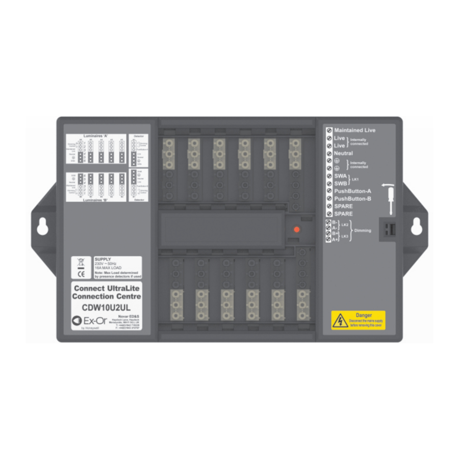
A red indicator in the connection chamber indicates that power is present.

Connections are made as illustrated. Two spare terminals are provided for termination purposes.
Live (Lin) is routed to the two detector connectors (A1 and B1).
Maintained Live (ML) is routed to the ten luminaire connectors, A2-A6 and B2-B6.
SWA is the switched live output from a detector connected to A1.
SWB is the switched live output from a detector connected to B1.
LK1 is a common connection between the switched live from each detector position. It must be removed to separate the luminaires into two groups.
Dimming Control Terminals
The Dimming Control signals from each detector to its group of luminaires are accessible at terminals under the connection chamber cover. Links are factory fitted to join the two groups on to one detector.
Dimensions

Height (H) = 50mm (108mm including plug and lead)
Width (W) = 315mm (361mm including mounting feet)
Depth (D) = 205mm
Fixing Centres (F) = 340mm
Weight = 1.85 kg
Detector Connection
There are two detector connection positions on each box. The detector is connected by a flying lead and GST18/7 plug.
Ensure max detector load is not exceeded

Luminaire Connection
There are ten luminaire outlets on each box. Each luminaire is connected by a flying lead and GST18/6 plug.

A simple schematic showing connection information (including two spare terminals) follows:

If sockets A1 and B1 are not occupied by presence detector, those sockets may be used for luminaires, however the plug will need to be 7-pole and wired appropriately.
Connection Examples
Single Detector with 10 Luminaires
(For load information, see Note under Technical Data)

Auxiliary Items
Luminaire Leads:
CPWL633 3m, 3-core, 6-pole GST 18/6 Plug & Ex-Or Latching Shell
CPWL635 5m, 5-core, 6-pole GST 18/6 Plug & Ex-Or Latching Shell
CPWL643 3m, 4-core, 6-pole GST 18/6 Plug & Ex-Or Latching Shell
CPWL645 5m, 4-core, 6-pole GST 18/6 Plug & Ex-Or Latching Shell
CPWL653 3m, 5-core, 6-pole GST 18/6 Plug & Ex-Or Latching Shell
CPWL655 5m, 5-core, 6-pole GST 18/6 Plug & Ex-Or Latching Shell
Emergency Luminaire Leads:
CPWL663 3m, 6-core, 6-pole GST 18/6 Plug & Ex-Or Latching Shell
CPWL665 5m, 6-core, 6-pole GST 18/6 Plug & Ex-Or Latching Shell
Plug & Latching Shell:
CPW7 GST 18/7 Plug & Ex-Or Latching Shell
Detectors:
MS1100PFSWCWL7 Bronze Series Detector with photocell for CDW10U2UL - slimline flush
MS1200PFSWCWL7 Silver Series Detector with photocell for CDW10U2UL - slimline flush
Two Detectors
(For load information, see Note under Technical Data)

Distribution Unit with Mains-Based 'OneTouch' Dimming
(for use with compatible Dimmable Ballasts)

(for use with compatible Digital Ballasts)

Notes:
- The dimming control connections are mains rated
- Unit must not be used with multi-phase connections
- Mains-based dimming must not be used in conjunction with Ex-Or's range of presence detectors.
Technical Data
OPERATING VOLTAGE: 230V 50Hz (UK & Europe)
PRODUCT RATING/RECOMMENDED CIRCUIT PROTECTION: 16 Amps
MAXIMUM LOAD PER OUTLET: 6 Amps*
MAXIMUM TOTAL LOAD: 16 Amps*
SUPPLY TERMINAL CAPACITY: 6.0mm (2 x 2.5mm )
DIMMING TERMINAL CAPACITY: 4.0mm2
CASE MATERIAL: Polycarbonate
CASE FINISH: Lightly textured light grey
*Note: These specifications relate to the product when used as a simple wiring device. When mains-switching presence detectors are used in conjunction with this equipment, it is the presence detectors which will normally dictate the maximum load. It is important to check, and not exceed, the specification of the current-switching presence detectors, which will typically be around 6 Amps.
Ex-Or
Novar ED&S Limited
Haydock Lane, Haydock, Merseyside WA11 9UJ
Tel: +44 (0)1942 719229 Fax: +44 (0)1942 272767
Email: technicalsales.ex-or@honeywell.com
www.ex-or.com

Documents / Resources
References
Download manual
Here you can download full pdf version of manual, it may contain additional safety instructions, warranty information, FCC rules, etc.
Download Ex-Or CDW10U2UL - Connection Centre Installation Manual
Advertisement

Need help?
Do you have a question about the CDW10U2UL and is the answer not in the manual?
Questions and answers