Table of Contents
Advertisement
Quick Links
R-410A
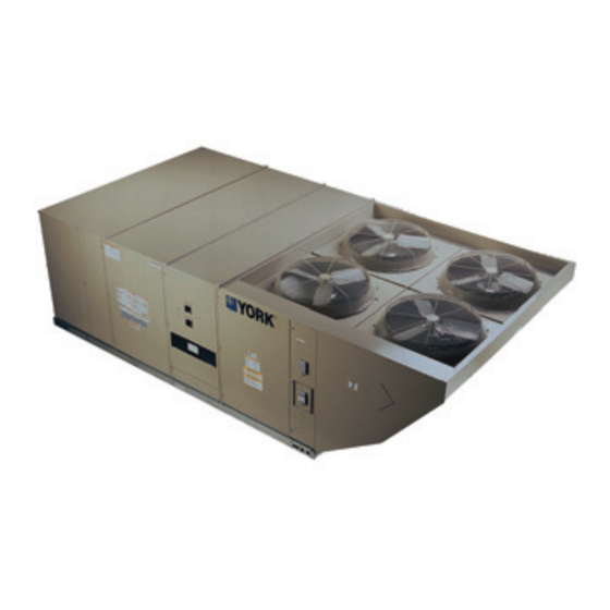
J15/20XP SERIES 20 W/SMART EQUIPMENT™
15/20 Ton
60 Hertz
General . . . . . . . . . . . . . . . . . . . . . . . . . . . . . . . . . . . . . . . . . . 2
Installation . . . . . . . . . . . . . . . . . . . . . . . . . . . . . . . . . . . . . . . . 5
Limitations . . . . . . . . . . . . . . . . . . . . . . . . . . . . . . . . . . . . 5
Location. . . . . . . . . . . . . . . . . . . . . . . . . . . . . . . . . . . . . . . . 7
Rigging And Handling . . . . . . . . . . . . . . . . . . . . . . . . . . . . . 7
Ductwork . . . . . . . . . . . . . . . . . . . . . . . . . . . . . . . . . . . . . . 13
Condensate Drain . . . . . . . . . . . . . . . . . . . . . . . . . . . . . . . 13
Compressors. . . . . . . . . . . . . . . . . . . . . . . . . . . . . . . . . . . 14
Filters . . . . . . . . . . . . . . . . . . . . . . . . . . . . . . . . . . . . . . . . 14
Power And Control Wiring. . . . . . . . . . . . . . . . . . . . . . . . . 14
Field Installed Electric Heat Accessories . . . . . . . . . . . . . 23
Options/Accessories . . . . . . . . . . . . . . . . . . . . . . . . . . . . . 23
Economizer Sequences . . . . . . . . . . . . . . . . . . . . . . . . . . 23
Dry Bulb Changeover . . . . . . . . . . . . . . . . . . . . . . . . . . . . 23
Single Enthalpy Changeover. . . . . . . . . . . . . . . . . . . . . . . 23
Dual Enthalpy Changeover . . . . . . . . . . . . . . . . . . . . . . . . 23
Auto. . . . . . . . . . . . . . . . . . . . . . . . . . . . . . . . . . . . . . . . . . 23
Free Cooling Operation. . . . . . . . . . . . . . . . . . . . . . . . . . . 23
Power Exhaust . . . . . . . . . . . . . . . . . . . . . . . . . . . . . . . . . 24
Setpoints . . . . . . . . . . . . . . . . . . . . . . . . . . . . . . . . . . . . . . 24
Inputs . . . . . . . . . . . . . . . . . . . . . . . . . . . . . . . . . . . . . . . . 24
Outputs . . . . . . . . . . . . . . . . . . . . . . . . . . . . . . . . . . . . . . . 24
1 J15/20XP Unit Limitations . . . . . . . . . . . . . . . . . . . . . . . . . 6
2 J15/20XP Unit Weight . . . . . . . . . . . . . . . . . . . . . . . . . . . . 8
3 J15/20XP Unit Accessory Weights . . . . . . . . . . . . . . . . . . 9
4 J15/20XP Unit Clearances . . . . . . . . . . . . . . . . . . . . . . . 12
5 Control Wire Sizes . . . . . . . . . . . . . . . . . . . . . . . . . . . . . . 15
6 Electrical Data . . . . . . . . . . . . . . . . . . . . . . . . . . . . . . . . . 17
7 J15/20XP Physical Data . . . . . . . . . . . . . . . . . . . . . . . . . 21
8 Electric Heat Minimum Supply Air . . . . . . . . . . . . . . . . . . 23
9 Smart Equipment™ Economizer Board Details . . . . . . . 25
10 Altitude/Temperature Correction Factors . . . . . . . . . . . . 30
1 J20XP Component Location . . . . . . . . . . . . . . . . . . . . . . 6
2 J20XP Unit 4 Point Load Weight . . . . . . . . . . . . . . . . . . . 8
3 J20XP Unit 6 Point Load Weight . . . . . . . . . . . . . . . . . . . 8
4 J15XP Unit 4 Point Load Weight . . . . . . . . . . . . . . . . . . . 8
5 J15XP Unit 6 Point Load Weight . . . . . . . . . . . . . . . . . . . 8
6 Center of Gravity . . . . . . . . . . . . . . . . . . . . . . . . . . . . . . . 8
7 J20XP Unit Dimensions Front View . . . . . . . . . . . . . . . . . 9
8 J15XP Unit Dimensions Front View . . . . . . . . . . . . . . . . 10
9 J15/20XP Unit Dimensions Rear View . . . . . . . . . . . . . . 11
10 J15/20XP Unit Dimensions Rain Hood . . . . . . . . . . . . . 12
11 J15/20XP Roof Curb . . . . . . . . . . . . . . . . . . . . . . . . . . . 12
12 Fixed Outdoor Air Damper . . . . . . . . . . . . . . . . . . . . . . . 13
TABLE OF CONTENTS
Operation . . . . . . . . . . . . . . . . . . . . . . . . . . . . . . . . . . . . . 24
Damper Set Point Adjustment . . . . . . . . . . . . . . . . . . . . . . 28
Air Balance . . . . . . . . . . . . . . . . . . . . . . . . . . . . . . . . . . . . 34
Sequence Of Operation . . . . . . . . . . . . . . . . . . . . . . . . . . . . . 36
Cooling Sequence Of Operation . . . . . . . . . . . . . . . . . . . . 36
Cooling Operation Errors . . . . . . . . . . . . . . . . . . . . . . . . 36
Electric Heating Sequence Of Operations. . . . . . . . . . . . . 37
Defrost Termination . . . . . . . . . . . . . . . . . . . . . . . . . . . . 38
Interval between Defrosts. . . . . . . . . . . . . . . . . . . . . . . . 38
Forced Defrost . . . . . . . . . . . . . . . . . . . . . . . . . . . . . . . . 38
Electric Heat Operation Errors . . . . . . . . . . . . . . . . . . . . 38
Start-Up (Cooling) . . . . . . . . . . . . . . . . . . . . . . . . . . . . . . . . . 39
Charging The Unit . . . . . . . . . . . . . . . . . . . . . . . . . . . . . . . . . 40
Maintenance . . . . . . . . . . . . . . . . . . . . . . . . . . . . . . . . . . . . . 41
Normal Maintenance . . . . . . . . . . . . . . . . . . . . . . . . . . . . . 41
Filters . . . . . . . . . . . . . . . . . . . . . . . . . . . . . . . . . . . . . . . . 41
Motors . . . . . . . . . . . . . . . . . . . . . . . . . . . . . . . . . . . . . . . . 41
Blower Shaft Bearing . . . . . . . . . . . . . . . . . . . . . . . . . . . . 41
Outdoor Coil . . . . . . . . . . . . . . . . . . . . . . . . . . . . . . . . . . . 41
Start-Up Sheet . . . . . . . . . . . . . . . . . . . . . . . . . . . . . . . . . . . . 48
LIST OF TABLES
11 Air Flow Performance - Side Duct Application . . . . . . . . 32
12 Air Flow Performance - Bottom Duct Application . . . . . . 33
13 RPM Selection . . . . . . . . . . . . . . . . . . . . . . . . . . . . . . . . 34
14 Indoor Blower Specifications . . . . . . . . . . . . . . . . . . . . . . 34
15 Power Exhaust Specifications . . . . . . . . . . . . . . . . . . . . . 34
16 Additional Static Resistance . . . . . . . . . . . . . . . . . . . . . . 35
17 Limit Control Setting . . . . . . . . . . . . . . . . . . . . . . . . . . . . 38
18 Electric Heat Anticipator Setpoint . . . . . . . . . . . . . . . . . . 39
19 Smart Equipment™ UCB Details . . . . . . . . . . . . . . . . . . 42
LIST OF FIGURES
13 Condensate Drain . . . . . . . . . . . . . . . . . . . . . . . . . . . . . 13
Electric Heat . . . . . . . . . . . . . . . . . . . . . . . . . . . . . . . . . . 15
15 Typical Field Wiring 24 Volt Thermostat . . . . . . . . . . . . 16
16 SE-ECO1001-0 Economizer Controller . . . . . . . . . . . . . 25
17 Belt Adjustment . . . . . . . . . . . . . . . . . . . . . . . . . . . . . . . 29
18 Altitude/Temperature Correction Factors . . . . . . . . . . . . 30
For All Unit Tonnages . . . . . . . . . . . . . . . . . . . . . . . . . . 34
20 J15XP (15 Ton) Charging Chart . . . . . . . . . . . . . . . . . . . 40
21 J20XP (20 Ton) Charging Chart . . . . . . . . . . . . . . . . . . . 40
22 Unit Control Board . . . . . . . . . . . . . . . . . . . . . . . . . . . . . 42
5168275-JIM-I-1121
Advertisement
Table of Contents

Subscribe to Our Youtube Channel
Summary of Contents for Johnson Controls York 20 Series
-
Page 1: Table Of Contents
R-410A J15/20XP SERIES 20 W/SMART EQUIPMENT™ 15/20 Ton 60 Hertz TABLE OF CONTENTS General ......... . 2 Operation . -
Page 2: General
This product must be installed in strict compliance with building, electrical, and mechanical codes. the enclosed installation instructions and any applicable local, state and national codes including, but not limited to, building, electrical, and mechanical codes. Johnson Controls Ducted Systems... - Page 3 • Smart Equipment™ Control Quick Start Guide - 1136326 operation of the product could cause personal injury or property damage. Renewal Parts For authorized replacement parts call Johnson Controls, Inc. National Source 1 Parts outlet at 1-866-523-9670. Approvals This system uses R-410A Refrigerant which operates at higher pressures than R-22.
- Page 4 5168275-JIM-I-1121 Nomenclature 15 & 20 Ton Johnson Controls Model Number Nomenclature J15 XP C A 2 A 1 Product Generation Nominal Cooling Capacity 1 = First Generation J15 = 15 Ton J20 = 20 Ton Cabinet Options A = Std Cabinet Product Category &...
-
Page 5: Installation
Ducted Systems @ 1-877-874-SERV for In U.S.A.: guidance. Additional accessories may be needed for National Electrical Code, ANSI/NFPA No. 70 - Latest stable operation at temperatures below 30°F. Edition Johnson Controls Ducted Systems... -
Page 6: J15/20Xp Unit Limitations
Lifting Holes Figure 1: J20XP Component Location Table 1: J15/20XP Unit Limitations Unit Limitations Size Unit Voltage SCCR (kVA) Applied Voltage Outdoor DB Temp (Tons) Max (°F) 208/230-3-60 460-3-60 (15) 575-3-60 208/230-3-60 460-3-60 (20) 575-3-60 Johnson Controls Ducted Systems... -
Page 7: Location
All panels must be secured in place when the unit is lifted. The condenser coils should be protected from rigging cable damage with plywood or other suitable material. Johnson Controls Ducted Systems... -
Page 8: J15/20Xp Unit Weight
Table 2: J15/20XP Unit Weight Size Weight (lbs.) Center of Gravity 4 Point Load Location (lbs.) 6 Point Load Location (lbs.) Model (Tons) Shipping Operating 15 (15) J**XP 2145 2140 77.1 20 (20) J**XP 2655 2650 88.8 Johnson Controls Ducted Systems... -
Page 9: J15/20Xp Unit Accessory Weights
Used For Diameter 1-1/8” KO Front Control Wiring 3/4” NPS (Fem.) Bottom 3-5/8” KO Front Power Wiring 3” NPS (Fem.) Bottom NOTE: All entry holes should be field sealed to prevent rain water entry into the building. Johnson Controls Ducted Systems... -
Page 10: J15Xp Unit Dimensions Front View
Used For Diameter 1-1/8” KO Front Control Wiring 3/4” NPS (Fem.) Bottom 3-5/8” KO Front Power Wiring 3” NPS (Fem.) Bottom NOTE: All entry holes should be field sealed to prevent rain water entry into the building. Johnson Controls Ducted Systems... -
Page 11: J15/20Xp Unit Dimensions Rear View
Remove and discard the bottom duct covers. Duct Connect ductwork to the flanges on those panels. openings are closed with sheet metal covers except when Johnson Controls Ducted Systems... -
Page 12: J15/20Xp Unit Clearances
3. If economizer is factory installed, the unassembled rain hood must be removed from its ride along position in front of the evaporator coil, or in the outdoor air compartment, prior to final installation. Note: Units and ductwork are approved for zero clearance to combustible material when equipped with electric heaters. 25-1/4" Figure 11: J15/20XP Roof Curb Johnson Controls Ducted Systems... -
Page 13: Ductwork
Figure 13: Condensate Drain possible. Cut an opening 16 inches high by 18 inches wide in the ductwork to accommodate the damper. Using the holes in the Johnson Controls Ducted Systems... -
Page 14: Compressors
Two-inch filters are supplied with each unit. For J20XP models, properly fused. the filter rack can be easily modified to accommodate four inch filters. Filters must always be installed ahead of the evaporator Johnson Controls Ducted Systems... -
Page 15: Control Wire Sizes
Refer to Table 5 for Table 5: Control Wire Sizes control wire sizing and maximum length. Wire Size Maximum Length 18 AWG 150 Feet 1. From the unit to the thermostat and back to the unit. Johnson Controls Ducted Systems... -
Page 16: Typical Field Wiring 24 Volt Thermostat
X is an input to the thermostat to display Error Status condi ons. Figure 15: Typical Field Wiring 24 Volt Thermostat 208/230-3-60 unit control transformers are factory wired for 230v power supply. Change tap on transformer for 208-3-60 operation. See unit wiring diagram. Johnson Controls Ducted Systems... -
Page 17: Electrical Data
57.2 21.7 84.3 460-3-60 17.9 43.3 84.3 84.3 86.6 111.3 NONE 42.2 17.3 63.8 575-3-60 12.8 34.6 63.8 63.8 69.3 85.5 1. Minimum Circuit Ampacity. 2. Dual Element, Time Delay Type. 3. HACR type per NEC. Johnson Controls Ducted Systems... - Page 18 62.2 21.7 89.3 460-3-60 17.9 43.3 89.3 89.3 86.6 116.3 NONE 46.2 17.3 67.8 575-3-60 12.8 34.6 67.8 67.8 69.3 89.5 1. Minimum Circuit Ampacity. 2. Dual Element, Time Delay Type. 3. HACR type per NEC. Johnson Controls Ducted Systems...
- Page 19 224.1 (20) NONE 21.7 87.1 460-3-60 17.9 12.5 43.3 87.1 87.1 86.6 114.1 NONE 44.4 17.3 575-3-60 12.8 34.6 69.3 87.7 1. Minimum Circuit Ampacity. 2. Dual Element, Time Delay Type. 3. HACR type per NEC. Johnson Controls Ducted Systems...
- Page 20 234.1 (20) NONE 21.7 92.1 460-3-60 17.9 12.5 43.3 92.1 92.1 86.6 119.1 NONE 48.4 17.3 575-3-60 12.8 34.6 69.3 91.7 1. Minimum Circuit Ampacity. 2. Dual Element, Time Delay Type. 3. HACR type per NEC. Johnson Controls Ducted Systems...
-
Page 21: J15/20Xp Physical Data
Circuitry Type Inter-twined Split-face Refrigerant control CONDENSER FAN DATA Quantity Fan diameter (Inch) Type Prop Prop Drive type Direct Direct No. speeds Number of motors Motor HP each 1.25 1140 1075 BELT DRIVE EVAP FAN DATA Quantity Johnson Controls Ducted Systems... - Page 22 12 - (12x 24 x 4) 4 - (16 x 20 x 4) 1. 2 In. Throwaway, Standard, MERV (Minimum Efficiency Reporting Value) 3. 2. 2 In. Pleated, Optional, MERV 8. 3. 4 In. Pleated, Optional, MERV 13. Johnson Controls Ducted Systems...
-
Page 23: Field Installed Electric Heat Accessories
• Return and outside air dry bulb and return and outside air Economizer Minimum Position humidity = dual enthalpy • If either the return or outside air dry bulb sensors are unreliable, free cooling is not available Johnson Controls Ducted Systems... -
Page 24: Power Exhaust
If the demand for cooling from the space/return is satisfied, the economizer output will modulate to minimum position and the compressor outputs will be de-energized as long as their minimum run timers have expired. Johnson Controls Ducted Systems... -
Page 25: Smart Equipment™ Economizer Board Details
Green UCB SA bus communication SA BUS SA BUS communication is currently active, off indicates the economizer transmission indicator board is awaiting SA bus communication SA BUS Pin connections at left on upper edge of economizer board Johnson Controls Ducted Systems... - Page 26 Frequency Fan. Used to turn on/enable the power exhaust fan motor. 24 VAC common/0-10 VDC negative for Connects through circuit trace to 24V~ IN pin COM economizer actuator 24V~ IN Pin connections at right on upper edge of economizer board Johnson Controls Ducted Systems...
- Page 27 24 VAC common/0-10 VDC negative for the air Connects through circuit trace to 24V~ IN pin COM monitoring station sensor 24 VAC hot supplied for the building pressure 24V~ Connects through circuit trace to 24V~ IN pin HOT sensor Johnson Controls Ducted Systems...
-
Page 28: Field Installed Bas-Ready Economizer Power Exhaust Damper Set Point Adjustment
IAQ Max damper position setting. 25 to 85 degrees open. When the signal exceeds its set point (Demand Control Ventilation Set Point) setting and there is a call for free cooling, Replace the economizer access panel. Johnson Controls Ducted Systems... -
Page 29: Belt Adjustment
Air density correction factors are shown in Table 10 and Figure 18. *Never Loosen (C)* Figure 17: Belt Adjustment Johnson Controls Ducted Systems... -
Page 30: Altitude/Temperature Correction Factors
This value must be corrected for elevation. Example 2: A system, located at 5,000 feet of elevation, is to deliver 6,000 CFM at a static pressure of 1.5". Use the unit BHP at 5,000 ft. = 3.2 x .832 = 2.66 Johnson Controls Ducted Systems... - Page 31 Size Motor Blower 6 Turns 5 Turns 4 Turns 3 Turns 2 Turns 1 Turn Fully Model (Tons) Sheave Sheave Open Open Open Open Open Open Closed 5.75 1VP60 BK110 8.63 1VP60 BK090 1035 1075 1120 Johnson Controls Ducted Systems...
-
Page 32: Air Flow Performance - Side Duct Application
9.38 1021 9.79 10000 9.29 9.87 1. Blower performance includes 2" filters only. See STATIC RESISTANCE table for additional applications. 2. See RPM SELECTION table to determine required motor sheave setting. 3. kW = BHP x 0.820. Johnson Controls Ducted Systems... -
Page 33: Air Flow Performance - Bottom Duct Application
9.45 1034 9.90 10000 999 10.01 1. Blower performance includes 2" filters only. See STATIC RESISTANCE table for additional applications. 2. See RPM SELECTION table to determine required motor sheave setting. 3. kW = BHP x 0.820. Johnson Controls Ducted Systems... -
Page 34: Air Balance
Failure to properly adjust the total system air quantity can result in extensive blower damage. After readings have been obtained, remove the tubes and reinstall the two 5/16” dot plugs that were removed in Step 1. Johnson Controls Ducted Systems... -
Page 35: Additional Static Resistance
2. The pressure drop through the economizer is greater for 100% outdoor air than for 100% return air. If the resistance of the return air duct is less than 0.25 IWG, the unit will deliver less CFM during full economizer operation. Johnson Controls Ducted Systems... -
Page 36: Sequence Of Operation
UCB will lock-out the associated compressor. If the other compressor is inactive, the condenser fans will be When energized, the indoor blower has a minimum run time of de-energized. 30 seconds. Johnson Controls Ducted Systems... -
Page 37: Electric Heating Sequence Of Operations
“R” and “W1”. This 24vac signal is fault as well. passed through the UCB to the RW1 Relay and the MV terminal on the UCB. Contacts RW1 open, assuring the reversing valve Johnson Controls Ducted Systems... -
Page 38: Defrost Termination
“ON” cycles manually initiated by selecting "Test Defrost" in the UCB menu. and may result in the lowering of the temperature within the conditioned space. Refer to Table 18 for the required electric heat anticipator setting. Johnson Controls Ducted Systems... -
Page 39: Start-Up (Cooling)
Check indoor blower rotation. Set the thermostat to the lowest temperature setting. • If blower rotation is in the wrong direction. Refer to Phasing Section in general information section. Turn “OFF” all electric power to unit. Johnson Controls Ducted Systems... -
Page 40: Charging The Unit
2. This chart is applicable to unit with the TXV's left to the factory setting. If the TXV's have been adjusted in the field, the charging chart may no longer apply. Figure 21: J20XP (20 Ton) Charging Chart Johnson Controls Ducted Systems... -
Page 41: Maintenance
If water is used to clean coil, be sure electric power to the unit is shut off prior to cleaning. NOTE: Exercise care when cleaning the coil so that the coil fins are not damaged. Johnson Controls Ducted Systems... -
Page 42: Smart Equipment™ Ucb Details
SD-24 and R 24 VAC hot return from factory accessory smoke Connects through circuit trace to the R terminal on the upper left SD R detector, condensate overflow and user shutdown of the board relay switching in series Johnson Controls Ducted Systems... - Page 43 10KΩ/2.5 VDC is 0°F offset, 0Ω/0 VDC is maximum potentiometer above offset and 20KΩ/3.4 VDC is maximum below offset from active space temperature setpoint Pin Temperature sensor connections at right on upper edge of UCB Johnson Controls Ducted Systems...
- Page 44 2-10 VDC (0-100%) output for the indoor blower blower VFD based on fan-only, cooling stage and heating stage Variable Frequency Drive outputs. For VAV units: this output provides control of the indoor blower VFD based on supply duct static pressure input and setpoint. Johnson Controls Ducted Systems...
- Page 45 Lockout” and C1 output is then prevented until alarm reset. HPS2 24 VAC hot out for refrigerant circuit 2 High Not effective for one stage compressor UCBs. Connects (right pin) Pressure Switch through circuit trace to the R terminal Johnson Controls Ducted Systems...
- Page 46 4-way Joystick for display menu navigation Item USB connector at right of UCB Used for backup, restoration, & copying of board parameters as Type A female Universal Serial Bus connector well as board software updating through a flash drive Johnson Controls Ducted Systems...
-
Page 47: Cable For Fc Buses And Sa Buses In Order Of Preference
2. We recommend 26 AWG solid, 6-wire (3 twisted pairs) cable as the best fit for fabricating modular cables with the modular jack housing assembly. Be sure the cable you use fits the modular jack housing. The preassembled cables that are available from Anixter (Part No. CBL-NETWORKxxx) use 24 gauge wire. Johnson Controls Ducted Systems... -
Page 48: Start-Up Sheet
5168275-JIM-I-1121 Start-Up Sheet Johnson Controls Ducted Systems... - Page 49 5168275-JIM-I-1121 Johnson Controls Ducted Systems...
- Page 50 5168275-JIM-I-1121 Johnson Controls Ducted Systems...
- Page 51 5168275-JIM-I-1121 Johnson Controls Ducted Systems...
- Page 52 5168275-JIM-I-1121 Johnson Controls Ducted Systems...
- Page 53 Subject to change without notice. Printed in U.S.A. 5168275-JIM-I-1121 Copyright © 2021 by Johnson Controls, Inc. All rights reserved. Supersedes: 5168275-JIM-H-0620 York International Corporation 5005 York Drive Norman, OK 73069...
Need help?
Do you have a question about the York 20 Series and is the answer not in the manual?
Questions and answers