Table of Contents
Advertisement
Quick Links
Advertisement
Chapters
Table of Contents

Related Manuals for Santec OTF-980

Summary of Contents for Santec OTF-980
- Page 1 Wavelength & Bandwidth Tunable Filter OTF-980 Operation Manual...
- Page 2 OTF-980 Operation Manual Notes to Users 1) Copyright 2015, Santec Corporation. All rights reserved. No part of this Operation Manual may be reproduced or transmitted in any form or by any means, electronic or mechanical, for any purpose, without the prior written permission of Santec.
- Page 3 Thank you for purchasing our product, Wavelength & Bandwidth Tunable Filter OTF- 980. This Instruction Manual contains information and precautions necessary for the operation of OTF-980. This manual is intended for those with sufficient knowledge to conduct the evaluation of laser danger and its safe control. Before operating OTF-980, you should first thoroughly read this Instruction Manual and become familiar with its contents.
- Page 4 Chapters 1 to 4 illustrate the outline of this product, safety precautions, and installation of the product. Chapters 5 describe how to operate the product. Santec recommends that Chapters 1 to 4 are read carefully before proceeding to this chapter.
- Page 5 Wavelength&Bandwidth Tunable Filter OTF-980 Explanation of Terms The meanings of the following terms used in this Operation Manual are defined as below: (1) Meaning DANGER This indicates pressing DANGER, and if it DANGER!! is not avoided, personnel death or serious injury results, therefore, it is the most emphasized special information.
- Page 6 OTF-980 Operation Manual Markings on the instrument This mark is used on the equipment as warning of danger.
-
Page 7: Table Of Contents
Wavelength&Bandwidth Tunable Filter OTF-980 Contents Introduction How to Read the Manual Explanation of Terms 1. Safety Information 2. Product Composition 3. Panel Description Front Panel Rear Panel Bottom Panel 4. Installation Operating Environments Power Supply 5. Basic Operation Turning on the Unit... - Page 8 6-3-2 Communication Conditions and System Requirements Command Reference 6-4-1 Common Commands 6-4-2 OTF-980 Status System 6-4-3 IEEE488.2 Common Commands - Detailed Description 6-4-4 OTF-980 Specific Command Overview 6-4-5 OTF-980 Specific Command – Detailed Description 6-11 6-4-6 Command Error 6-21 Sample Program 6-22 7.
-
Page 9: Safety Information
Wavelength&Bandwidth Tunable Filter OTF-980 Safety Information Please note the following points when utilizing the instrument in order to protect and prevent instrument failure. DANGER!! As for this product, when the laser is input from INPUT, the laser is output from OUTPUT. - Page 10 OTF-980 Operation Manual...
-
Page 11: Product Composition
Wavelength&Bandwidth Tunable Filter OTF-980 Product Composition This product is composed of the OTF-980 body and accessories. Check to make sure that all the following items are included. Power cord OTF-980 body Inspection report Operation Manual Check to make sure that the product body and the accessories have no scratches or stains. - Page 12 OTF-980 Operation Manual...
-
Page 13: Panel Description
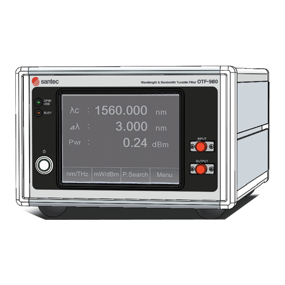
Wavelength&Bandwidth Tunable Filter OTF-980 Panel Descriptions 3-1 Front Panel Operation Touch panel condition LED Optical input connector Optical output connector Power switch Figure3-1. Front View 3-2 Rear Panel GPIB Ethernet Main power switch Power inlet Exhaust fan Nameplate Figure3-2. Back View... -
Page 14: Bottom Panel
OTF-980 Operation Manual 3-3 Bottom Panel Air Inlet Rubber legs Figure3-3. Bottom View... -
Page 15: Installation
CAUTION Be sure to install the OTF-980 in a level place (less than 5 degree). It is recommended to install this product on a vibration-proof base. The unit may not operate correctly if the device is set in an inclined position. -
Page 16: Power Supply
OTF-980 Operation Manual 4-2 Power Supply This product uses a 3-line power cord and plug with a protective ground line. Power cord may be attached and detached, Connect it to the power source socket at the rear panel. Use the power cord supplied with the unit. Do not use the inappropriate power code. -
Page 17: Basic Operation
1. When the unit is powered on it will enter its start up sequence. During this sequence the Santec logo will be displayed on the touch panel (as seen below). 2. When the start up sequence has finished, the main screen will be displayed (See below). -
Page 18: Optical Fiber Connection
Before connecting the input light, check that the optical power does not exceed the maximum specified level for the OTF-980. The maximum level is +27dBm. If the optical input exceeds this limit, there is a risk of damage to the OTF-980’s internal optical elements. -
Page 19: Keypad Layout
Wavelength&Bandwidth Tunable Filter OTF-980 ■ 5-3-2 Keypad Layout Use the keypad to input numerical values. Figure5-3-2. Keypad Input Screen... -
Page 20: Menu Navigation
OTF-980 Operation Manual ■ 5-3-3 Menu Navigation Pressing the “Menu” button will allow you to cycle through all of the available “Function” buttons (see below). Figure5-3-3. Menu Navigation Table 5-1. Button Display and Explanation nm/THz Changes between wavelength mode and frequency mode mW/dBm Changes the power unit of measure. -
Page 21: Lcd Operations Available From The Touch Panel
Wavelength&Bandwidth Tunable Filter OTF-980 5 -4 LCD Operations Available from the Touch Panel ■ 5-4-1 Setting the GPIB Touching the GPIB button will display the “GPIB connection properties” screen. From this screen it s possible to change the following 2 parameters: GPIB Address Touching the address area will display the keypad. -
Page 22: Setting The Lan
OTF-980 Operation Manual ■ 5-4-2 Setting the LAN Touching the LAN button will display the LAN connection properties screen. The following 6 parameters are displayed: • Physical Address This address is particular to the unit, so it cannot be changed. -
Page 23: Power Monitor
Wavelength&Bandwidth Tunable Filter OTF-980 ■ 5-4-3 Power Monitor Touching the mW/dBm button will change the power unit of measure between mW and dBm. Touching it once more will return it to the previous unit of measure. ■ 5-4-4 Peak Search 1) Initiate the Peak Search Function Touching the P.Search button will display the “Peak Search Options”... - Page 24 OTF-980 Operation Manual The keypad will then be displayed. Touch the number you wish to adjust. A blinking box will appear around the selected number. Use the keypad to adjust the number. The adjustable range is limited to the tuning range of the unit.
- Page 25 Wavelength&Bandwidth Tunable Filter OTF-980 2-3) Executing Peak Search Pressing the “Execute” button from the “Peak Search Settings” screen will start the peak search. The progress of the peak search can be confirmed by looking at either the “λ curr” area or the progress bar.
-
Page 26: Setting The Wavelength
OTF-980 Operation Manual ■ 5-4-5 Setting the Wavelength Touch anywhere within the “center wavelength” area. The keypad will be displayed. The number that was touched will blink. Adjust the wavelength with the keypad. 5-10... -
Page 27: Setting The Bandwidth
Wavelength&Bandwidth Tunable Filter OTF-980 ■ 5-4-6 Setting the Bandwidth Touch anywhere within the “bandwidth” area. The keypad will be displayed. The number that was touched will blink. Adjust the Bandwidth with the keypad. ■ 5-4-7 Setting the Frequency Pressing the “nm/THz” button will switch the unit into frequency mode. -
Page 28: Setting The Offset
OTF-980 Operation Manual ■ 5-4-8 Setting the Offset This function can be used when either the center wavelength offset or the bandwidth offset needs to be corrected. Touching the “Offset” button will display “Wavelength Offset” screen. 1) Center Wavelength Offset Touch anywhere in the “Wavelength”... -
Page 29: Additional System Information Ajusting The Lcd Backlight
Wavelength&Bandwidth Tunable Filter OTF-980 2) Bandwidth Offset Touch anywhere in the “Bandwidth” area. The keypad will be displayed. You can adjust the value at this time. ■ 5-4-9 Additional System Information Adjusting the LCD backlight 1) Displaying the System Information Touching the “Info.”... - Page 30 OTF-980 Operation Manual 2) Displaying the Maintenance Information Touching the “Maint.” button will display the maintenance information. The following 4 parameters will be displayed: • Wave Pulse Counter • Band Pulse • System Temperature • Board Temperature 3) Adjusting the Display Backlight Touching the “Dimmer”...
-
Page 31: Operation By Communication
Wavelength&Bandwidth Tunable Filter OTF-980 Operation by Communication CAUTION Before inserting and extracting the connectors for the communication cables, make sure to turn off the power to the device to avoid damaging the device. This device supports GPIB and USB as means of communication. Available commands vary according to the communication method used. -
Page 32: Gpib Function
GP-IB has 10 kinds of interface functions, each of which has its grade that is called its subset. A "0" after the symbol of each function shows that support is not made, and each numeric value represents grade. Table 6-1. Subset of OTF-980 Symbol Function... -
Page 33: Usb
Wavelength&Bandwidth Tunable Filter OTF-980 6-2 USB ■ 6-2-1 Connection Connect the B-type connector cable to the USB connector on the rear panel. USB connector Figure 6-2. USB connector ■ 6-2-2 Communication Conditions and System Requirements USB controller: Mfd. by Future Technology Devices International Ltd. -
Page 34: Command Reference
Default Gateway : *.*.*.* (* = integer from 0 〜 255) DHCP Option Support Port No. : Integer from 0 〜 65535 6-4 Command Reference OTF-980 has common commands based on the IEEE488.2 standards, and unique commands for the OTF-980. Explanation of each command follows. ■ 6-4-1 Common Commands Available for IEEE488.2 common commands in the following list. -
Page 35: Otf-980 Status System
Wavelength&Bandwidth Tunable Filter OTF-980 ■ 6-4-2 OTF-980 Status System The following status systems with four registers are provided. I. Status Byte Register (STBR) II. Service Request Enable Register (SRER) III. Standard Event Status Register (SESR) IV. Standard Event Enable Register (SEER) 1) Status System Structure Overview Figure 6-4. - Page 36 OTF-980 Operation Manual RQS (Request Service Bit): RQS is set when a Service Request is issued. ESB (Event Status Bit): ESB is set when any of the bits of the Standard Event Status Register (SESR) is set. MAV (Message Available Bit): MAV is set when output data is prepared.
-
Page 37: Ieee488.2 Common Commands -Detailed Description
Wavelength&Bandwidth Tunable Filter OTF-980 ■ 6-4-3. IEEE488.2 Common Commands –Detailed Description 1) *IDN? Identification Query Syntax *IDN? Description A query to identify the device; places strings of device information such as the name, firmware, and version in the output queue. - Page 38 OTF-980 Operation Manual 5) *OPC? Operation Complete Query Syntax *OPC? Description Places 1 in the output queue when all operation processing has completed. Response 0: (In operation) 1: (Operation completed) 6) *CLS Clear Status Syntax *CLS Description Clears all event registers and queues (except for the output queue) and reflects the summary in the Status Byte Register.
- Page 39 64 and the value of the Status Byte Register (since Bit 6 is set in the serial poll). ■ 6-4-4. OTF-980 Specific Command Overview An overview of the specific commands is shown in the following table. Table 6-3. OTF-980 Specific Command List...
- Page 40 OTF-980 Operation Manual [:CONFigure]:WAVelength Sets the filter center wavelength. 6-13 Reads out the setting value of the [:CONFigure]:WAVelength? 6-13 filter center wavelength. [:CONFigure][:WAVelength]:FREQuency Sets the filter center frequency. 6-14 Reads out the setting value of the [:CONFigure][:WAVelength]:FREQuency? 6-14 filter center frequency.
-
Page 41: Otf-980 Specific Command - Detailed Description
Wavelength&Bandwidth Tunable Filter OTF-980 ■ 6-4-5 OTF-980 Specific Command – Detailed Description Specific commands are described in detail as follows. 1) System related commands :SPECial:REBoot Syntax :SPECial:REBoot Description Resets the device. Parameter None Response None Example :SPEC:REB [:STATus]:OPERation:CONDition? Syntax :SPECial:REBoot Description Reads out the state of the device. - Page 42 OTF-980 Operation Manual :SYSTem:VERSion? Syntax :SYSTem:VERSion? Description Reads out the version of the firmware. Parameter None Response The format is (4 digits) + (period) + (4 digits) ****.**** Example :SYST:VERS? → 0001.0000 :SYSTem:COMMunicate:GPIB:ADDRess Syntax :SYSTem:COMMunicate:GPIB:ADDRess<wsp><value> Description Sets the GPIB address.
-
Page 43: Sets The Filter Center Wavelength
Wavelength&Bandwidth Tunable Filter OTF-980 :SYSTem:COMMunicate:GPIB:DELimiter? Syntax :SYSTem: COMMunicate: GPIB:DELimiter? Description Reads out the command delimiter for GPIB communication. Parameter None Response 0: CR 1: LF 2: CR+LF 3 : NONE Example : SYST:COMM:GPIB:DEL? → +1 Indicates that the GPIB delimiter is ”LF”. -
Page 44: Sets The Filter Center Frequency
OTF-980 Operation Manual [:CONFigure] [:WAVelength]:FREQuency Syntax [:CONFigure][:WAVelength]:FREQuency <wsp><value> Description Sets the filter center wavelength in frequency. Parameter Minimum acceptable frequency to Maximum acceptable frequency (Unit : THz/None) Also allowed: MIN: Minimum programmable value MAX: Maximum programmable value Step : 0.00001 (Unit : THz/GHz/MHz/None) -
Page 45: Sets The Offset To The Filter Center Wavelength
Wavelength&Bandwidth Tunable Filter OTF-980 [:CONFigure]:OFFSet[:WAVelength][:VALue] Syntax [:CONFigure]:OFFSet[:WAVelength] <wsp><value> Description Sets the offset to the filter center wavelength. Parameter Range: Minimum offset wavelength to Maximum offset wavelength. (Unit : pm/nm/um/None) Also allowed: MIN: Minimum programmable value MAX: Maximum programmable value Step : 1E-12... -
Page 46: Sets The Filter Bandwidth
OTF-980 Operation Manual [:CONFigure]:BANDwidth Syntax [:CONFigure]:BANDwidth <wsp><value> Description Sets the filter bandwidth. Parameter None Response Range: Minimum setting bandwidth to Maximum setting bandwidth (Unit: pm/nm/um/None) Also allowed: MIN: Minimum programmable value MAX: Maximum programmable value Step : 1E-12 Example : BAND 2nm : BAND 2.0E-09... -
Page 47: Sets The Center Wavelength For Peak Search
Wavelength&Bandwidth Tunable Filter OTF-980 [:CONFigure]:OFFSet:BANDwidth[:VALue]? Syntax [:CONFigure]:OFFSet:BANDwidth[:VALue]? [MIN|MAX] Description Reads out the offset bandwidth of filter bandwidth. Parameter None: Reads out the currently set offset bandwidth. MIN: Reads out the minimum acceptable offset bandwidth. MAX: Reads out the maximum acceptable offset bandwidth. -
Page 48: Sets The Peak Search Span
OTF-980 Operation Manual [:SENSe][:WAVelength]:SPAN Syntax [:SENSe][:WAVelength]:SPAN <wsp><value> Description Sets the peak search span. Parameter Range: 0 ~ (Maximum setting wavelength – Minimum setting wavelength) (Unit: pm/nm/um/None) Step: 1E-12 Response None Example :SPAN 40nm :SPAN 0.04um :SPAN 4.000000E-08 Sets the peak search span to 40nm. -
Page 49: Sets The Power Unit
Wavelength&Bandwidth Tunable Filter OTF-980 [:SENSe]:POWer:UNIT Syntax [:SENSe]:POWer:UNIT <wsp><value> Description Sets the power unit. Parameter 0: dBm 1: mW Response None Example :POW:UNIT 0 Sets the power unit to “dBm”. [:SENSe]:POWer:UNIT? Syntax [:SENSe]:POWer:UNIT? Description Reads out the power unit. Parameter None... - Page 50 OTF-980 Operation Manual Table 6-4. Operating Status List Operating Status Value Not used Not used Not used Not used Not used Not used Not used Not used Not used Not used Not used Not used In Peak Search operation In setting operation of the bandwidth...
-
Page 51: Command Error
Wavelength&Bandwidth Tunable Filter OTF-980 ■ 6-4-6.Command Error Errors issued are stored as error messages in the error queue and can be read out with the ”:SYSTem:ERRor?” command. The list is as shown in Table6-6 Command Error List. Table 6-6. Command Error List... -
Page 52: Sample Program
OTF-980 Operation Manual 6-5 Sample Program This is a sample program on Microsoft Visual Basic Ver6.0. Sets the bandwidth to 1nm and changes the wavelength from 1530nm to 1610nm with step width 1nm and executes the peak search every time. - Page 53 Wavelength&Bandwidth Tunable Filter OTF-980 ‘Changes the wavelength from 1530nm to 1610nm with step width 1nm For wav = 1530 To 1610 Step 1 ‘Sets the wavelength Call ibwrt(ud, “WAV “ & CStr(wav) & “nm” & vbCrLf) ‘Waits the operation completion Call MotorChk ‘Sets the center wavelength for peak search...
- Page 54 OTF-980 Operation Manual Call ibwrt(ud, “PS?” & vbCrLf) ans = “” Call ibrd(ud, ans) ‘Check the operation completion Loop Until Val(ans) = 0 End Sub 6-24...
-
Page 55: Operating Principles
Wavelength&Bandwidth Tunable Filter OTF-980 Operating Principles Figure7-1. OTF-980 Block diagram This device is a bench-top tunable filter that allows both center wavelength and passband width tuning simultaneously and independently. Unique precision free-space optics and an accurate tuning mechanism deliver excellent optical control and a topflat passband shape. - Page 56 OTF-980 Operation Manual The input light is collimated by an optical fiber collimator, and then passes to the diffractive grating. From the grating, the light travels through the lens on to the high reflective mirror surface. Wavelength tuning and bandwidth tuning is done by the moving the mirror to control the amount of reflected light.
-
Page 57: Specifications
Wavelength&Bandwidth Tunable Filter OTF-980 Specifications Table 8-1. OTF-980 Specifications... - Page 58 OTF-980 Operation Manual...
-
Page 59: Maintenance
Connection of the optical fiber with dust and dirt on the end of the optical connector of OTF-980 cause loss of optical output, therefore, clean the connector periodically. The optical adapter arranged at the optical connector may be pulled out by removing the locking latches, therefore, remove it and clean the end of the optical connector. -
Page 60: Inspection/Calibration
9- 3 Inspection/Calibration OTF-980 is warranted for a period of one year. Inspection and calibration on a regular basis (once every 12 months) is recommended. Please contact our Sales Department concerning requests for instrument inspection/calibration or consultation on other matters. -
Page 61: Re-Packing And Shipping
Wavelength&Bandwidth Tunable Filter OTF-980 Re-packing and Shipping Special attention for re-packing and shipping is required when you ship the instrument for repair or to a remote location. 10-1 Re-packing Please make sure that the original shipping box is used during the shipment, according to the following instructions. - Page 62 OTF-980 Operation Manual 10-2...
-
Page 63: Troubleshooting
Wavelength&Bandwidth Tunable Filter OTF-980 Troubleshooting Fault condition Cause Action No power Power cord is unconnected. Connect power cord properly Change power cord. Main power switch is shut off. Turn on the main power switch on rear panel. Wavelength (Frequency) Setting out of range. - Page 64 Santec Photonics Laboratories. Our telephone number and facsimile number are shown below.
Need help?
Do you have a question about the OTF-980 and is the answer not in the manual?
Questions and answers