
Related Manuals for ADLINK Technology EMU-200 Series

Summary of Contents for ADLINK Technology EMU-200 Series
- Page 1 EMU-200 Series Arm-based IoT Gateway / Arm 架構 IoT 閘道器 User’s Manual Manual Rev.: 0.17 Nov. 6, 2023 Revision Date: Part No: 50M-19701-1000...
- Page 2 Revision History Revision Release Date Description of Change(s) 0.17 2023-11-06 Next draft...
- Page 3 EMU-200 Series Preface Copyright © 2023 ADLINK Technology Inc. This document contains proprietary information protected by copy- right. All rights are reserved. No part of this manual may be repro- duced by any mechanical, electronic, or other means in any form without prior written permission of the manufacturer.
- Page 4 California Proposition 65 Warning WARNING: This product can expose you to chemicals including acrylamide, arsenic, benzene, cadmium, Tris(1,3-dichloro-2-propyl)phosphate (TDCPP), 1,4-Diox- ane, formaldehyde, lead, DEHP, styrene, DINP, BBP, PVC, and vinyl materials, which are known to the State of California to cause cancer, and acrylamide, benzene, cadmium, lead, mercury, phthalates, toluene, DEHP, DIDP, DnHP, DBP, BBP, PVC, and vinyl materials, which are known to the State of California to cause...
- Page 5 EMU-200 Series BSMI Warning 警告 : 為避免電磁干擾,本產品不應安裝或使用於住宅環境 NCC Warning 取得審驗證明之低功率射頻器材,非經核准,公司、商號或使用者 均不得擅自變更頻率、加大功率或變更原設計之特性及功能。 低功率射頻器材之使用不得影響飛航安全及干擾合法通信;經發現 有干擾現象時,應立即停用,並改善至無干擾時方得繼續使用。 前述合法通信,指依電信管理法規定作業之無線電通信。 低功率射頻器材須忍受合法通信或工業、科學及醫療用電波輻射性 電機設備之干擾。 1. 應避免影響附近雷達系統之操作。 2. 高增益指向性天線只得應用於固定式點對點系統。 FCC Warning Any changes or modifications not expressly approved by the party responsible for compliance could void your authority to operate the equipment.
- Page 6 interference received, including interference that may cause undesired operation. RF exposure statements 1. This Transmitter must not be co-located or operating in conjunction with any other antenna or transmitter. 2. This equipment complies with FCC RF radiation exposure limits set forth for an uncontrolled environment. This equipment should be installed and operated with a minimum distance of 20 centimeters between the radiator and your body or nearby persons.
- Page 7 EMU-200 Series specified for point-to-point and non-point-to-point operation as appropriate; and The high-power radars are allocated as primary users (i.e. priority users) of the bands 5650-5850 MHz and that these radars could cause interference and/or damage to LE-LAN devices. Avertissement: 1) Le dispositif fonctionnant dans la bande 5150-5250 MHz est réservé...
- Page 8 Antenna Gain (dBi) Antenna Type Ant 0 Ant 1 2.4G WiFi 2400~2483.5 MHz Dipole 2.04 1.74 5150~5350 MHz Dipole 2.14 2.14 5G WiFi 5470~5725 MHz Dipole 2.04 2.04 5725~5850 MHz Dipole 2.33 2.33 Taiwan RoHS Declaration viii Preface...
-
Page 9: Table Of Contents
Functional Block Diagram............ 4 Mechanical Drawings............5 I/O Connectors..............10 2 Getting Started ..............17 Unpacking the EMU-200 Series ........17 Connecting to I/O ............... 18 Connecting/Disconnecting Power........19 Checking Device Status and Connection ......20 Usage Scenarios ............... 21 3 EGiFlow ................ - Page 10 Important Safety Instructions..........71 Consignes de Sécurité Importantes ........73 Getting Service ..............77...
-
Page 11: List Of Figures
EMU-200 Series List of Figures Figure 1-1: Functional Block Diagram........... 4 Figure 1-2: EMU-200 Series Dimensions ........5 Figure 1-3: DIN Rail Mount 1 ............6 Figure 1-4: DIN Rail Mount 2 ............7 Figure 1-5: Wall Mount 1............... 8 Figure 1-6: Wall Mount 2............... - Page 12 Figure 3-30: Create AWS.............. 43 Figure 3-31: Configure AWS ............43 Figure 3-32: Create Python iApp........... 44 Figure 3-33: Select a template and enter a name......44 Figure 3-34: The new iApp can be edited ........45 Figure 3-35: Run a new iApp ............45 Figure 3-36: Network Settings............
-
Page 13: Introduction
Ethernet or serial-based proto- cols allowing for wider integration of devices into a network with the ability to send data to the cloud. The EMU-200 Series is designed to work under a large variety of applications such as monitoring energy consumption, solar power monitoring, and smart manufacturing. -
Page 14: Specifications
1.3 Specifications Model EMU-200 EMU-200-W System Processor ARM Cortex A9 1.0 GHz Memory 1 GB DDR3 NAND Flash (eMMC) 32 GB eMMC WiFi 2.4GHz/5GHz Debian 11 Configuration Interface EGiFlow Interface I/O Interface Ethernet 2x RJ45 10BASE-T/100BASE-TX/1000BASE-T ports Serial Ports 2x RS-232/422/485, 300 bps to 115.2 kbps 2x USB 2.0 Type-A (front panel) 5 (2x WiFi, 2x LTE, 1x GNSS) Antenna... - Page 15 EMU-200 Series Model EMU-200 EMU-200-W Certifications CE/FCC/ICES-003/RCM/BSMI, Class A EN 55032, EN 55035, EN 61000-6-2, EN 61000-6-4, CNS 15936 Safety IEC/EN/UL 62368-1 CE-RED (EN 300328, EN300440, EN 301489 -1/-17, EN301893), RCM, FCC, ISED, NCC Model EMU-200-W Function Frequency Maximum Output Power (EIRP)
-
Page 16: Functional Block Diagram
1.4 Functional Block Diagram DDR3 DDR3L SDRAM 1GB eMMC 32GB SDIO SD Card Connector SDIO WIFI Antenna Connector WiFi Module USB 2.0 USB 2.0 Connector USB 2.0 GPS Antenna Connector USB 2.0 Connector Antenna Connector USB 2.0 M.2 Connector USB 2.0 Micro SIM slot USB 2.0 Hub USB 2.0... -
Page 17: Mechanical Drawings
EMU-200 Series 1.5 Mechanical Drawings All dimensions are in millimeters unless noted. NOTE: NOTE: 1.5.1 Dimensions 110.90 Figure 1-2: EMU-200 Series Dimensions... -
Page 18: Figure 1-3: Din Rail Mount 1
1.5.2 DIN Rail Mounting The DIN rail mount can be attached to the EMU-200 Series with two M4 x 5mm screws included in the mounting kit. Figure 1-3: DIN Rail Mount 1... -
Page 19: Figure 1-4: Din Rail Mount 2
EMU-200 Series Figure 1-4: DIN Rail Mount 2... -
Page 20: Figure 1-5: Wall Mount 1
1.5.3 Wall Mounting Each wall mount bracket can be attached to the EMU-200 Series two M4 x 5mm screws included in the mounting kit. 5.20 Figure 1-5: Wall Mount 1 5.20 Figure 1-6: Wall Mount 2... -
Page 21: Figure 1-7: Wall Mount 3
EMU-200 Series 33.25 Figure 1-7: Wall Mount 3... -
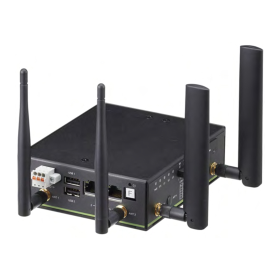
Page 22: I/O Connectors
1.6 I/O Connectors The EMU-200 Series provides rich peripherals, including: 2 RS-232/422/485 ports (COM1, COM2) 2 Gigabit Ethernet ports 1 microSD slot 1 Micro-SIM slot 2 USB 2.0 Type-A ports 5 antenna ports ... - Page 23 1000 Link/Activity (Tx, Rx) 100 Link/Activity (Tx, Rx) 10 Link/Activity (Tx, Rx) Table 1-2: Active/Link/Speed LED Indicators 1.6.2 LED Indicators The EMU-200 Series has nine LEDs located on the front panel. Function Description Power input OFF: Device is not powered (Green) ...
- Page 24 1.6.3 USB 2.0 Ports The EMU-200 Series provides two USB 2.0 Type-A ports. All USB ports are compatible with high-speed, full-speed and low-speed USB devices. USB ports can be used to add a USB dongle. 1.6.4 Reset Button Restore the EMU-200 Series to factory default settings using a paper clip or similar item inserted into the reset pin hole and press- ing the reset button until the device reboots.
-
Page 25: Figure 1-8: Com Port Pin Definition
EMU-200 Series 1.6.6 COM Port Connectors The EMU-200 Series provides four COM ports through 5-pin con- nectors. The COM1 & COM2 ports support RS-232/422/485 modes. (Default RS-485) Figure 1-8: COM Port Pin Definition Signal RS-232 RS-422 RS-485 TXD- DATA- TXD+... -
Page 26: Figure 1-9: Dc Power Input
1.6.7 DC Power Input Figure 1-9: DC Power Input Signal V+ (DC_IN) Table 1-4: DC Power Input Pin Definition Use an approved power source as certified by IEC or UL. If you need an adaptor, optional accessories or further assistance, con- tact ADLINK for further information. - Page 27 Micro-SIM Slot Insert a micro-SIM card into the slot. Make sure it is properly aligned and inserted all the way. Once the card is inserted, the EMU-200 Series can connect to a cellular network and access the Internet. 1.6.9 microSD Slot Insert a microSD card into the slot for additional storage.
- Page 28 This page intentionally left blank.
-
Page 29: Getting Started
EMU-200 Series Getting Started 2.1 Unpacking the EMU-200 Series Ensure that the following items are included in the package. If any items are missing, contact your sales representative for assistance. EMU-200 Series DIN rail mount kit with 2x flat head screws ... -
Page 30: Connecting To I/O
2.2 Connecting to I/O 1 For serial ports, insert the signal wires into the terminal block. 2. Use a CAT 5 type Ethernet cable to connect a host PC to one of the Ethernet ports on the top panel. -
Page 31: Connecting/Disconnecting Power
2. Turn on the power source. If the power was connected correctly, the front panel green PWR LED will light up. If the EMU-200 Series needs to be shut down, turn off the power source. To remove the power wires, use a flat head screwdriver to push the orange slots on the terminal block and then pull out the wires. -
Page 32: Checking Device Status And Connection
2. Wait for the SYS LED to display solid green after power- ing on to confirm that the operating system kernel is ready. 3. Connect LAN2 of the EMU-200 Series to the host com- puter. 4. Set the network domain of the host computer to 192.168.50.xx. -
Page 33: Usage Scenarios
EMU-200 Series 2.5 Usage Scenarios The EMU-200 Series is designed as a distributed protocol transla- tor for different devices via ethernet/wireless communication and can be used in many kinds of scenarios. Choose the most suitable scenario depending on your system infrastructure. The EMU-200 Series is provided with three kinds of software support: ... - Page 34 This page intentionally left blank.
-
Page 35: Egiflow
EMU-200 Series access EGiFlow via one of the default following options. Option 1: With a host PC connected to the EMU-200 series LAN2 port, do the following: 1. Set the host PC’s network setting to Static IP mode. -
Page 36: Figure 3-1: Egiflow Login Page
A unique default hostname is generated for each EMU-200 series device and can be found on the label of the box it was shipped in. The hostname can be changed from EGiFlow (default username: admin, default password: adlink). Figure 3-1: EGiFlow Login Page... -
Page 37: Egiflow Menu
EMU-200 Series 3.2 EGiFlow Menu EGiFlow includes the following items for configuration and protocol translation in different field applications. EGiFlow iApp Modbus TCP/RTU to AWS and Azure Modbus TCP/RTU to MQTT Modbus TCP/RTU to RESTful ... -
Page 38: Figure 3-3: Create Egiflow Iapp
3.2.1 EGiFlow iApp EGiFlow iApp provides an intuitive and straightforward configura- tion method, allowing the EMU-200 Series to acquire the required sensor data for measurement through various communication pro- tocols. It then converts and transmits the data to various services,... -
Page 39: Figure 3-4: Modbus Tcp/Rtu To Cloud
EMU-200 Series Modbus TCP/RTU to AWS and Azure The overall architecture of the application is shown below, aiming to acquire sensor data from the Modbus interface and send it to cloud services such as Azure and AWS. Figure 3-4: Modbus TCP/RTU to Cloud... -
Page 40: Figure 3-5: Create Modbus Tcp
To achieve this, you can utilize EGiFlow iApp as a middleware component. 1. Modbus TCP Client (Master): Use EGiFlow iApp's intu- itive setup to create and configure the Modbus TCP cli- ent (master) functionality. Specify the Modbus server's IP address, port number, and other necessary parameters. EGiFlow iApp provides an interface to define the data registers to be read from the Modbus server. -
Page 41: Figure 3-7: Create Modbus Rtu
EMU-200 Series 2. Modbus RTU Master: Use EGiFlow iApp's setup to cre- ate and configure the Modbus RTU Master functionality. Determine the serial parameters required for communi- cation, such as baud rate, parity, data bits, and stop bits. EGiFlow iApp provides an interface to define the data registers to be read from the Modbus slave. -
Page 42: Figure 3-9: Create Compute
3. Data Conversion by Compute: Upon receiving the sen- sor data from the Modbus server/slave, EGiFlow iApp can perform any required data conversions or formatting as per the specific requirements of Azure and AWS. This may include transforming the data into the appropriate format, applying data preprocessing or aggregation, and ensuring compatibility with the cloud service APIs. -
Page 43: Figure 3-11: Create Azure
EMU-200 Series 4. Data Transmission to Azure: EGiFlow iApp can utilize Azure IoT Hub to securely transmit the converted sensor data. It establishes a connection with Azure and pub- lishes the data to the desired Azure endpoint. Figure 3-11: Create Azure... -
Page 44: Figure 3-13: Create Aws
5. Data Transmission to AWS: Similarly, EGiFlow iApp can leverage AWS IoT Core to securely transmit the converted sensor data. It establishes a connection with AWS and publishes the data to the desired AWS end- point. Figure 3-13: Create AWS Figure 3-14: Configure AWS... -
Page 45: Figure 3-15: Run And Deploy
EMU-200 Series 6. Run and Deploy: Click Run and wait for the deployment to finish. Figure 3-15: Run and Deploy Modbus TCP/RTU to MQTT The overall architecture of the application is in Figure 3-16, with the objective of acquiring sensor data from the Modbus interface and transmitting it via MQTT to an Edge Server or Local SCADA. - Page 46 To accomplish this, you can follow the steps below using EGiFlow iApp: 1. Modbus TCP Client (Master): Use EGiFlow iApp's setup to create and configure the Modbus TCP client (master) functionality. Specify the Modbus server's IP address, port number, and other necessary parameters. EGiFlow iApp provides an interface to define the data registers to be read from the Modbus server.
-
Page 47: Figure 3-17: Create Mqtt Publish
EMU-200 Series 4. MQTT Communication: EGiFlow iApp integrates MQTT functionality to connect to an MQTT broker. It estab- lishes a connection with the broker and publishes the converted sensor data as MQTT messages. The MQTT broker can be located on the Edge Server or within the Local SCADA environment. -
Page 48: Figure 3-19: Modbus Tcp/Rtu To Restful
Modbus TCP/RTU to RESTful The overall architecture of the application is in Figure 3-19, with the objective of acquiring sensor data from the Modbus interface and transmitting it via RESTful API to an Edge Server or Local SCADA. Figure 3-19: Modbus TCP/RTU to RESTful To achieve this, you can follow the steps below using EGiFlow iApp: 1. -
Page 49: Figure 3-20: Create Restful
EMU-200 Series registers to be read from the Modbus slave. (See Figure 3-7 and Figure 3-8) 3. Data Conversion by Compute: Upon receiving the sen- sor data from the Modbus server/slave, EGiFlow iApp can perform any required data conversion or formatting to prepare it for RESTful API transmission. -
Page 50: Figure 3-21: Configure Restful
Figure 3-21: Configure RESTful 5. Run and Deploy: Click Run and wait for the deployment to finish. (See Figure 3-15) Modbus RTU to Modbus TCP The overall architecture of the application, as shown in Figure 3-22, aims to convert Modbus RTU to Modbus TCP. Figure 3-22: Modbus RTU to Modbus TCP 1. -
Page 51: Figure 3-23: Create Modbus Tcp Write
EMU-200 Series 2. Modbus TCP Conversion: Modbus RTU requests are recieved from the RTU devices and converted into Mod- bus TCP requests. Figure 3-23: Create Modbus TCP Write Figure 3-24: Configure Modbus TCP Write... -
Page 52: Figure 3-25: Opc Ua To Aws
OPC UA to AWS The overall architecture of the application is in Figure 3-25. Figure 3-25: OPC UA to AWS... -
Page 53: Figure 3-26: Create Opc Ua
EMU-200 Series To achieve this, you can follow the steps below using EGiFlow iApp: 1. OPC UA Client: Use EGiFlow iApp's intuitive setup to create and configure the OPC UA client functionality. Specify the OPC UA server's IP address, port number, and other necessary parameters. -
Page 54: Figure 3-28: Create Compute
2. Data Conversion by Compute: Use EGiFlow iApp's setup to create python functions, import OPC UA server data from the drop-down menu, reference sample code or write your own algorithms. Figure 3-28: Create Compute Figure 3-29: Develop Customized Data Conversion... -
Page 55: Figure 3-30: Create Aws
EMU-200 Series 3. Data Transmission to AWS: Establishes a connection with AWS and publishes data to the desired AWS endpoint. Figure 3-30: Create AWS Figure 3-31: Configure AWS 4. Run and Deploy: Click Run and wait for the deployment to finish. (See Figure 3-15) -
Page 56: Figure 3-32: Create Python Iapp
3.2.2 Python iApp This section includes a tutorial on how to create an iApp before deployment. iApps are saved in a repository and can be deployed to devices. 1. Create and Development: Click iApp Creator from the left sidebar and select Python iApp. 2. -
Page 57: Figure 3-34: The New Iapp Can Be Edited
EMU-200 Series Figure 3-34: The new iApp can be edited 3. Run and Deploy: Click Run and wait for the deployment to finish. Figure 3-35: Run a new iApp... -
Page 58: Figure 3-36: Network Settings
3.2.3 Gateway Configuration & Management LAN Network Settings The EMU-200 Series has two Ethernet ports that can be config- ured to support IPv4 and IPv6 network modes. 1. Open the Network Settings page. Figure 3-36: Network Settings 2. Select a LAN Port to set the wired network information. -
Page 59: Figure 3-38: Configure Lan Port
EMU-200 Series 3. Configure the DHCP or static IP settings. Figure 3-38: Configure LAN Port Figure 3-39: Select DHCP or Static... -
Page 60: Figure 3-40: Configure Static Ip (Ipv4)
Figure 3-40: Configure Static IP (IPv4) Figure 3-41: Configure Static IP (IPv6) -
Page 61: Figure 3-42: Dns Settings (Ipv4)
EMU-200 Series 4. For DNS settings, The DNS server will be used first. Figure 3-42: DNS Settings (IPv4) WiFi Network Settings Similar to the Ethernet port, the WiFi network client mode also supports IPv4 and IPv6 network mode settings. 1. Open the Network Settings page. -
Page 62: Figure 3-44: Wifi Network Information
2. Select to set WiFi network information. Figure 3-44: WiFi Network Information 3. Users need to select the SSID name and security of the WLAN to join the network. Figure 3-45: Select SSID Name 4. Click Apply to complete the configuration. -
Page 63: Figure 3-46: Cellular Network
EMU-200 Series Cellular Network Settings (Optional) 1. Open the Network Settings page, and select to set Cel- lular network information. Figure 3-46: Cellular Network 2. Make sure the system has a 4G LTE module and SIM card installed, and then enable the cellular network. -
Page 64: Figure 3-48: Select Time Settings
Time Sync Setting, NTP Users can adjust the time synchronization settings. 1. Double click Time Settings to enter the configuration page. Figure 3-48: Select Time Settings 2. The selection of synchronization with the NTP server allows the device to synchronize with a source, and the address of the source can be a domain name or an IP address. -
Page 65: Figure 3-50: Configure Ntp Settings
EMU-200 Series Figure 3-50: Configure NTP Settings Figure 3-51: Synchronize Time 3. Check serve as a NTP server to enable the device to be a time synchronization source for other devices to syn- chronize their time with this device. -
Page 66: Figure 3-52: Serial Settings
Serial Settings This page manages serial settings. 1. Double click Serial Settings to enter the configuration page. Figure 3-52: Serial Settings 2. Select the serial port to configure it. Figure 3-53: Configure Serial Port... -
Page 67: Figure 3-54: Account Management
EMU-200 Series Account Management This page manages user accounts. 1. Double click Account Management to enter the config- uration page. Figure 3-54: Account Management 2. Create user accounts and access privileges. Figure 3-55: Create User Accounts... -
Page 68: Figure 3-56: System Management
System Management This page manages restoring to factory defaults and firmware upgrades. 1. Double click System Management to enter the configu- ration page. Figure 3-56: System Management 2. Factory default: Restores the EMU-200 to factory default settings. 3. Firmware upgrade: A firmware upgrade file can be uploaded to the EMU-200 through this feature. -
Page 69: Figure 3-58: Event Log
EMU-200 Series Event Log This page manages the system log. 1. Double click Event Log to enter the page. Figure 3-58: Event Log 2. The log information includes Date Time, Level, Module and Message. Figure 3-59: Event Log Information... -
Page 70: Figure 3-60: External Storage
External Storage This page manages external storage. 1. Double click External Storage to enter the page. Figure 3-60: External Storage 2. Manage external storage. Figure 3-61: Manage External Storage... -
Page 71: Figure 3-62: System Information
EMU-200 Series System Information This page manages system information. 1. Double click System Information to enter the page. Figure 3-62: System Information 2. System information includes device information and soft- ware version. Figure 3-63: Device Information and Software Version... - Page 72 This page intentionally left blank.
-
Page 73: A Appendix: Debian Linux Os
EMU-200 Series Appendix A Debian Linux OS Debian Linux is used as the EMU-200 Series operating system for system integrators to develop customization applications.This appendix includes information on the following items. Connecting and Logging in via SSH User LED Control ... -
Page 74: User Led Control
4. Log in by username and password Enter the username: root Enter the password: adlink 5. You have successfully connected to the EMU-200 Series. A.2 User LED Control Turn on/Turn off User LED1 with the following commands: $ cd /sys/class/leds/led_user1g Turn on: $ echo 1 >... -
Page 75: Serial Port Configuration
EMU-200 Series A.3 Serial Port Configuration Use the following command to check the current Serial Port Inter- face. $ cat /etc/com_mode.conf The first row is COM1, the second row is COM2. Use the following command to set the Serial Port to RS-422 mode. - Page 76 Follow the steps below to set the Serial Device in Minicom to /dev/ ttyXRUSB1, so that dev/ttyXRUSB0 is COM1 and /dev/ ttyXRUSB1 is COM2. 1. Enter the command: $ minicom -s 2. Select Serial port setup. 3. Select Serial Device and configure the parameters for the COM port.
-
Page 77: Changing The Static Ip
EMU-200 Series A.4 Changing the Static IP Enter the following command. $ vi /etc/network/interfaces After entering the screen, press 'i' to enter edit mode and modify the IP address of eth1. After making the changes, press <Esc>, type :wq and then press <Enter>... -
Page 78: Lte Module Configuration And Connection (Optional)
A.6 4G LTE Module Configuration and Connection (optional) 1. Enter the following command for the 4G network dial-up settings (Module: QUECTEL/EM05-CE). $ modemon quectel Alternatively, enter the following command for the 4G network dial-up settings with a Sierra 4G LTE module. $ modemon sierra... - Page 79 EMU-200 Series 2. Enter the following command to check if the 4G network interface (ppp0) appears. $ ifconfig 3. Enter the following command to execute a 4G Network- ing Functional Test (ping Google DNS). $ ping -I ppp0 8.8.8.8...
-
Page 80: Wifi Configuration And Connection
A.7 WiFi Configuration and Connection 1. Enter the following EMU-200 search WIFI device com- mand. $ dmesg | grep wl 2. Enter the following command to the following path to modify WIFI AP and password. $ vi /etc/wpa_supplicant/wpa_supplicant.conf After entering the screen, press 'i' to enter edit mode to make changes. - Page 81 EMU-200 Series 4. Enter the following command to turn on the WiFi and connect to the access point (AP). $ wpa_supplicant -B -i wlan0 -c /etc/ wpa_supplicant/wpa_supplicant.conf 5. Enter the following command to automatically configure the IP address. $ udhcpc -i wlan0...
- Page 82 6. Enter the following command to check if wlan0 is config- ured with an IP address before connecting to the inter- net. $ ifconfig 7. Enter the following command to add a new route (based on the automatically configured IP address, changing the last octet to 1) to set a gateway (gw) for wlan0, as it needs a gateway to establish a connection to the exter- nal network.
- Page 83 EMU-200 Series Important Safety Instructions For user safety, please read and follow all instructions, Warnings, Cautions, and Notes marked in this manual and on the associated device before handling/operating the device, to avoid injury or damage. Read these safety instructions carefully.
- Page 84 A Lithium-type battery may be provided for uninterrupted backup or emergency power. Risk of explosion if battery is replaced with one of an incorrect type; please dispose of used batteries appropriately. Risque d’explosion si la pile est remplacée par une autre de CAUTION: type incorrect.
- Page 85 EMU-200 Series Consignes de Sécurité Importantes Pour la sécurité de l'utilisateur, veuillez lire et suivre toutes les instructions, avertissements, mises en garde et notes marqués dans ce manuel et sur l'appareil associé avant de manipuler/ d'utiliser l'appareil, afin d'éviter toute blessure ou tout dommage.
- Page 86 Fixez le cordon d'alimentation (ne placez aucun objet sur le cordon d'alimentation) Installez/fixez et utilisez l'appareil uniquement sur des surfaces stables et/ou sur les fixations recommandées Cet appareil est alimenté par un adaptateur ou une source DC. Veuillez vous assurer que l'adaptateur ou la source DC est relié...
- Page 87 EMU-200 Series Il est recommandé d'installer l'appareil uniquement dans une salle de serveurs ou une salle informatique où l'accès est: Réservé au personnel de service qualifié ou aux utilisa- teurs familiarisés avec les restrictions appliquées à l'emplacement, aux raisons de ces restrictions et toutes les précautions requises...
- Page 88 6450 Via Del Oro, San Jose, CA 95119-1208, USA Tel: +1-408-360-0200 Toll Free: +1-800-966-5200 (USA only) Fax: +1-408-600-1189 Email: info@adlinktech.com ADLINK Technology (China) Co., Ltd. 300 Fang Chun Rd., Zhangjiang Hi-Tech Park Pudong New Area, Shanghai, 201203 China Tel: +86-21-5132-8988 Fax: +86-21-5132-3588 Email: market@adlinktech.com ADLINK Technology GmbH Hans-Thoma-Straße 11...
Need help?
Do you have a question about the EMU-200 Series and is the answer not in the manual?
Questions and answers