Table of Contents
Advertisement
Quick Links
Advertisement
Table of Contents

Summary of Contents for Mindman CM10 Series
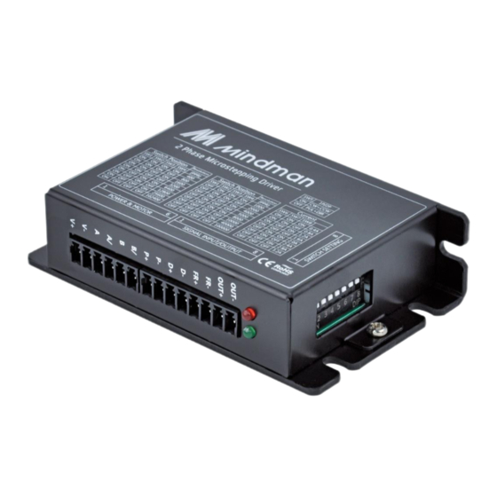
- Page 1 DRIVER Series CM10 User Manual Open Loop Stepper Motor Driver Ver. 202309...
-
Page 2: Table Of Contents
Content 1. Preamble................................... 1 1.1 Caution ................................ 1 1.2 Caution for safety ............................ 1 2. Technical specifications ............................4 2.1 Driver Specifications ..........................4 2.2 Motor Specifications ..........................5 2.3 Dimensions..............................6 3. System Configuration ............................7 3.1 CN1(Power & Motor) ..........................7 3.2 CN2(Signal Input/Outout) ........................ -
Page 3: Preamble
1. Preamble 1.1 Caution ① Please observe the ratings and use this product in the environment stated in this book. ② The purpose of designing and manufacturing the company's products is not to enable this product to be used in life-related situations or environments. Therefore, if you purchase this product for a special purpose, please inform our sales staff, discuss and confirm it. - Page 4 Danger Do not touch the terminal part and its interior with your hands when the power is on. ⚫ Otherwise, electric shock accidents may occur. Do not pull or twist the cable, or place heavy objects on the cable. Otherwise, electric ⚫...
- Page 5 Prohibit Do not use or store this product in a place exposed to direct sunlight. ⚫ Do not use or store this product in places where the surrounding temperature and ⚫ humidity exceed the specified range. Do not use or store this product in places with a lot of dust. ⚫...
-
Page 6: Technical Specifications
Technical specifications Driver Specifications Model CM10 Series Input Voltage (Driver) 20VDC~30VDC (Recommend 24VDC) Operating Current 0.4A, 0.8A, 1.2A, 1.6A, 2.0A, 2.4A, 2.8A, 3.2A (by DIP setting) Applicable Motor Two-phase hybrid stepping motor (Without Encoder) Control Method Single/Double pulse input Pulse Signal Optocoupler Input Voltage : H = 3.5 ~ 26V, L = 0 ~ 0.8V... -
Page 7: Motor Specifications
2.2 Motor Specifications Model OBM Series Size ☐20 ☐25 ☐28 Drive Bi-polar Method Phase 2 Phase Phase Current Holding N‧m 0.036 0.09 0.09 Torque Rotor Inertia g·cm Weight Insulation Mohm 100 MIN.(at 500VAC) Resistance Operation ℃ 0~50 Temperature ※If the operating current of the driver is higher than the rated current of the motor, long- term operation may cause damage to the motor. -
Page 8: Dimensions
2.3 Dimensions... -
Page 9: System Configuration
3. System Configuration 3.1 CN1(Power & Motor) Name Function V+ Drive Power : DC24V V- Drive Power : 0V Motor Wire OUTPUT : A Motor Wire OUTPUT : A/ Motor Wire OUTPUT : B Motor Wire OUTPUT : B/ 3.2 CN2(Signal Input/Outout) Name Function P+... -
Page 10: Dip Setting
3.3 DIP Setting Resolution Mode Current 3.3.1 Resolution Dip switch 1,600 3,200 6,400 12,800 25,600 102,400 1,000 2,000 4,000 5,000 8,000 10,000 40,000 100,000... -
Page 11: Current
3.3.2 Current Dip switch Phase Current 0.4 A 0.8 A 1.2 A 1.6 A 2.0 A 2.4 A 2.8 A 3.2 A ※When the driver has no pulse input for 500 milliseconds, the current will automatically drop to 50% of the set current, which is the factory default value to reduce motor heating. When pulse input is effective, the current returns to the set value. -
Page 12: Regenerative Discharge
flashing One red and two green Motor Motor is not connected. Disconnected flashing One red and three green Overvoltage Power input is more than 50V. flashing One red and four green Undervoltage Power input is less than 18V. flashing One red and five green Others Other alarm flashing... -
Page 13: Motor Connection
5. Motor connection When the motor is connected to the driver, please make sure that the power is turned off. Make sure that the unused wires are not short-circuited with other objects. The motor cannot be disconnected while the driver is energized. Do not connect the motor leads to the ground or power supply. -
Page 14: Motor Free:fr+/Fr
ahead of the pulse signal input, so as to avoid the wrong response of the driver to the pulse signal. When the motor switches the direction of rotation, it must be switched after the motor stops. The switching direction signal must be changed between the last pulse of the current direction signal ends and the first pulse of the next direction. -
Page 15: Typical Signal Connection
6.4 Typical Signal Connection Controller Driver NPN 型 Controller Driver PNP 型 Controller Driver ※The P, D and FR terminals have current limiting functions, which can be directly connected to the input signal without the external series resistor step-down current-limiting protection. The Vcc value is 3.5~26V. -
Page 16: Output Signal
7. Output Signal 7.1 Digital output circuit (Relay connection) Caution: When the relay is connected, both terminals of the relay must be connected to a diode. For example, 1N4001. 7.2 Digital output circuit (Optocoupler connection) The alarm output is photoelectrically isolated, with a maximum withstand voltage of 30VDC and a maximum saturation current of 50mA. -
Page 17: Pulse/Direction Input Timing Chart
8. Pulse/Direction input timing chart Single Pulse Input Pulse Input DIR Input Differential (Double Pulse) Input Pulse Input DIR Input... -
Page 18: Wiring Requirements
Wiring Requirements In order to prevent the driver from being interfered, it is recommended that the control signal use an anti-interference cable and the shield layer is grounded. Except for special requirements, the shield line of the control signal line should be grounded at a single side.
Need help?
Do you have a question about the CM10 Series and is the answer not in the manual?
Questions and answers