
Summary of Contents for Danley DNA SC48
- Page 1 DNA SC48 Processor Danley Sound Labs DNA SC48 Precision Audio DSP System Controller User Guide Version 6 (For firmware version 1.353 and above)
-
Page 2: Table Of Contents
FEDERAL COMMUNICATIONS COMMISSION NOTICE ................. 7 FOR CUSTOMERS IN CANADA ......................8 Thanks and Unpacking ..........................9 Unpacking the Danley Sound Labs DNA SC48 series controller............9 INSTALLATION INSTRUCTIONS ......................10 The User Guide............................11 Introduction and Key Features ......................12 Introduction ............................ - Page 3 Delay ............................. 24 High Pass Filter ..........................24 Parametric Equalisation ........................ 24 FIR Shelving EQ..........................24 Parametric Filters .......................... 24 Routing ............................25 Output ............................... 25 AES3 outputs ..........................25 Gain and Polarity ........................... 25 Delay ............................. 25 High and Low pass Filters ......................25 LIR Crossover Filtering ........................
- Page 4 AUX Port ............................30 Latency delay ............................ 33 Input/Output Latencies ......................... 33 Processing Latencies ........................33 Secure Mode ............................. 34 Overlay Flush ............................. 34 Processing Block Diagram ........................35 Input Menu Map Utility Menu Map ..................36 Output Menu Map ..........................38 EQ and Filter Response Graphs ......................
-
Page 5: Important Safety Instructions
IMPORTANT SAFETY INSTRUCTIONS Read these instructions. Keep these instructions. Heed all warnings. Follow all instructions. Do not use this apparatus near water. Clean only with dry cloth. Do not block any ventilation openings. Install in accordance with the manufacturer's instructions. Do not install near any heat sources such as radiators, heat registers, stoves or other apparatus (including amplifiers) that produce heat. - Page 6 SAFETY WARNING Permanent disconnection from the mains supply is to be achieved by removing the supplied cord connector from the back of the unit. SAFETY WARNING Do not remove any covers, loosen any fixings or allow items to enter any aperture. SAFETY WARNING Objects filled with liquids should not be placed on this apparatus.
-
Page 7: Compliance
COMPLIANCE FOR CUSTOMERS IN EUROPE This product complies with both the LVD (electrical safety) 73/23/EEC and EMC (electromagnetic compatibility) 89/336/EEC directives issues by the commission of the European community. Compliance with these directives implies conformity with the following European standards: EN60065 Product safety EN55103-1... -
Page 8: For Customers In Canada
communications. However, there is no guarantee that interference will not occur in a particular installation. If this equipment does cause harmful interference to radio or television reception, which can be determined by turning the equipment off and on, the user is encouraged to try and correct the interference by one or more of the following measures: •... -
Page 9: Thanks And Unpacking
Thanks and Unpacking Thank you for choosing a Danley Sound Labs DNA SC48 advanced system controller for your application. Please spare a little time to study the contents of this manual, so that you obtain the best possible performance from this unit. -
Page 10: Installation Instructions
INSTALLATION INSTRUCTIONS THIS PRODUCT MUST BE EARTHED. Use only a flexible cable or cord provided with a green or green and yellow core which must be connected to the protective earthing terminal of a suitable mains plug or the earthing terminal of the installation. The cord must be of maximum length 7.5 meters, rated SJ, SJT, or SJE, 10A minimum and be marked VW-1. -
Page 11: The User Guide
This user manual gives a progressively more detailed description of the functions of the Danley Sound Labs DNA SC48 series advanced system controller. A single page quick reference guide is provided for those users who are experienced with this type of equipment and just need to know how to ‘drive’... -
Page 12: Introduction And Key Features
High performance ‘universal mains’ switch mode power supply, designed in-house Drive Modules The DNA SC48 processor has a new way of ordering and grouping channels in order to give a more loudspeaker-based approach to controlling, designing and recalling loudspeaker configurations;... - Page 13 Drive Modules may be included in Module Groups, which use the Parameter Overlay feature in the SC48 to achieve trouble-free Grouping in the System Engineer application. The Presets in the SC48 are Drive-Module centric, and are used to configure individual Drive Modules rather than the whole device.
-
Page 14: Audio Connections
Audio Connections Input Connections For each input channel there is a female XLR input connector. Even channel numbers are for Analog inputs only. Odd channel numbers are either for Analog inputs (when in Analog input mode) or for AES3 input pairs (when in AES3 input mode). The HOT, +, or ‘in polarity’... -
Page 15: Using Unbalanced Connections
Using unbalanced connections Please note that the use of unbalanced connections is not recommended, however, when connecting the device to an unbalanced audio source, the signal conductor should be connected to XLR pin 2. The ‘Cold’ conductor or cable screen should be connected to XLR pin 3 with a short connection made between pin 1 and pin 3. -
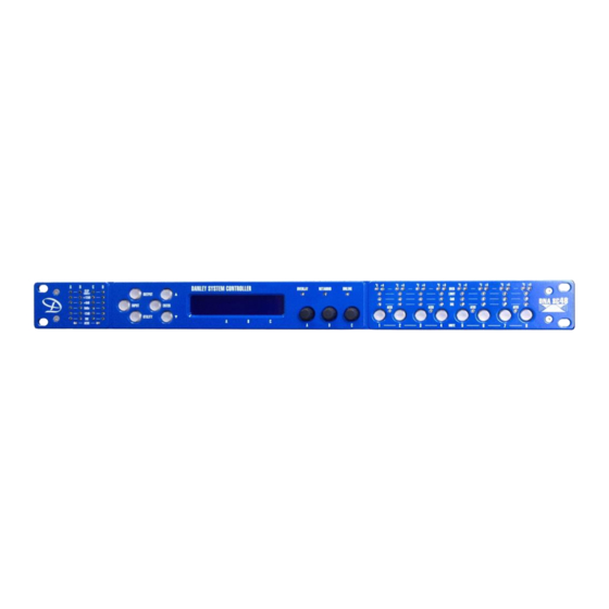
Page 16: Panel Layouts
Panel Layouts Limiter Indicators- The output indicators show the status of the limiter and output level. The <SIG> indicator shows signal presence and will illuminate when a signal is present in the output. The second indicator <-6dB> shows that the signal has reached 6dB below the limiter threshold. - Page 17 Networked Audio Ports- The DNA SC48 has the option for networked audio ports; if none are required a blanking plate will be fitted. There are several options for networked audio including Dante™ and AES 67. For a full list please consult your vendor.
-
Page 18: Operation
Operation Starting up the unit The unit will power up as soon as power is applied to the IEC power inlet; there is no power switch. When power is present the unit will go through its start-up cycle - first all the indicators will illuminate then go off, while the screen displays the boot loader information. -
Page 19: Drive Modules
Output 8 component number Drive Modules The DNA SC48 uses Drive Modules to represent loudspeaker sub-systems. Drive modules result in a less processor-centric and more loudspeaker-orientated system design. A drive module is defined as the processing provided by one Input DSP, and a number of outputs, which are associated with one- another by means of routing. - Page 20 Snapshot. Such a Module cannot be saved in a Module Preset. Note: DSP inputs are not the same as physical inputs. The DNA SC48 has four audio inputs and four DSP inputs. This is a matrix mixing system where any physical inputs, be they analog, AES3 or networked audio feeds, can drive any number of DSP inputs.
-
Page 21: Navigation And Designing Crossovers
Navigation and Designing Crossovers The DNA SC48 has 50 Drive Module preset locations. These can be stored and recalled from the <INPUT> pages, for the channel being viewed. To design a new crossover, press the desired <INPUT> or <OUTPUT> button to enter the pages where the parameters for each of the channels are shown. -
Page 22: Storing Module Presets
Storing Module Presets Once a drive module has been created it can be stored by pressing the <INPUT> button until the edited channel is reached, then pressing the down <> button until store page is reached. Using encoder “A” will change the preset number. When the destination preset is reached, pressing the <ENTER>... -
Page 23: Input
Also see Snapshots. Input AES3 / Network Inputs In addition to the usual analog inputs, the SC48 can also accept AES3 digital inputs. The same physical XLR sockets are used for both Analog and AES3 inputs; the function of these being determined by the Source parameters in the Input Route menu. -
Page 24: Gain And Polarity
Gain and Polarity The gain page of the input channel selected allows users to increase or decrease the amount of signal going into the selected input. Using encoder “A” will change the value in 0.2dB steps from -40dB to +20dB. The presence of an active Group Overlay parameter is indicated by the ‘[]’ symbol (See Overlays). -
Page 25: Routing
controlled by encoder “B” and ranges from 0.10 octaves to 5.2 octaves. Bandwidth can be shown and adjusted as Q or Octaves (Oct). Gain is controlled by encoder “C” and is adjusted in 0.2dB increments. The presence of an active Group Overlay parameter is indicated by the ‘[]’ symbol being appended to the Gain value. -
Page 26: Lir Crossover Filtering
Utilities. Limiters The DNA SC48 includes three limiters in the output signal path. Please note that whilst the Limiters in this product offer protection for amplifiers and drivers, they can never protect from all possible scenarios, therefore Danley Sound Labs is not responsible for any damage which might occur. - Page 27 When VX mode is engaged, the user can choose the crossover point of a ‘virtual crossover’, which incorporates two limiters per output so the user can individually limit the drivers in a passive 2-way enclosure using individual thresholds, and optimised attack and release characteristics for each. The Threshold of the second ‘Hi’...
-
Page 28: Amplifier Gain
A further parameter “Min” may also be available for more advanced applications. This allows the increasing limiting action at lower frequencies to level-off below a certain frequency. In most application, this would be left set to its default value of 5Hz. Amplifier Gain Expressed in dB, this is the gain of the amplifier which the output of the SC48 is feeding. -
Page 29: Store Snapshot
Store Snapshot This page of the “UTILITY” menu allows a Snapshot of the device to be stored. Also see Snapshots. Recall Snapshot This page of the “UTILITY” menu allows a Snapshot to be recalled. Also see Snapshots Port. Bandwidth Units This page of the “UTILITY”... -
Page 30: Static-Ip
Static-IP If the device or the computer has a static IP address set, System Engineer may not be able to 'see' the device if it is in a different IP Address range (i.e. in a different subnet). Unless there are good reasons it is best to avoid the use of static IP addressing if at all possible. - Page 31 • None - No operation 2+Mute (Event or State) – Either Snapshot 1 or Snapshot 2 may be recalled by applying a • momentary or static connection to an Aux port terminal, or the device may be muted by Grounding both Aux port terminals 3 Snaps (Event or State) –...
- Page 32 The following table shows the action taken for various Aux connection patterns in the various Aux port modes: AUX X AUX Y 2+Mute ACTION 3 Snaps ACTION 4 Snaps ACTION 3+Mute ACTION (State or Event) (State or Event) (State) (State) Open Open No Change...
-
Page 33: Latency Delay
Latency delay All Digital Signal Processing, and conversion between different formats of signal – analog/digital/network etc, necessarily introduce some delay (latency) to the signal path. Of course, we strive to minimise these latencies. Small as they are, it is sometimes useful to know their precise values. -
Page 34: Secure Mode
Example: Input/Output Analog Input 0.385ms Analog Output 0.402ms Processing Input HiShelf FIR (Off) LIR Linear Phase crossover (500Hz) 2.38ms VxLim Lim (VX mode on, 1KHz Fsplit) 0.358ms Total 3.525ms Note that the latencies within a Drive Module are equalised among outputs of that Drive Module. That is, padding delay will be automatically added to some outputs such that the total latency is the same in each output of a Drive Module. -
Page 35: Processing Block Diagram
Processing Block Diagram... -
Page 36: Input Menu Map Utility Menu Map
Input Menu Map Utility Menu Map CH A CH B CH C CH D FIR/ FIR/ FIR/ FIR/ HOME HOME HOME HOME HOME EQ 2 EQ 2 EQ 2 EQ 2 HOME EQ 1 EQ 1 EQ 1 EQ 1 HOME EQb\ EQb\... - Page 37 STATIC IP IP MODE IP CURR IP CURR UTIL STEREO HOME STYLE EQ BW SCREEN RECAL SNAP STOR SNAP MENU PAGE MENU BUTTON CHANNEL NO. UP/DOWN BUTTON PRESS MENU BUTTON PRESS...
-
Page 38: Output Menu Map
Output Menu Map …. CH 1 CH 2 CH 8 EQ / EQ / EQ / EQ / HOME EQ 8 EQ 8 EQ 8 EQ 8 HOME EQ 7 EQ 7 EQ 7 EQ 7 HOME EQ 6 EQ 6 EQ 6 EQ 6 HOME... -
Page 39: Eq And Filter Response Graphs
EQ and Filter Response Graphs... -
Page 43: Technical Specifications
Technical Specifications Input Impedance: Greater than 10,000 Ohm balanced Output Impedance: Less than 100 Ohm, impedance balanced Maximum Input level: +20dBu Maximum Output level: +18dBu into 600 Ohms Sample rate: 96kHz AES3 Input sample rate: 28kHz – 108kHz AES3 Output sample rate: 96kHz Frequency Response: 10Hz - 40kHz Input Dynamic range: Greater than 120dBa Typ. -
Page 44: Options
Options There is internal provision for digital audio network option cards to be factory fitted. Currently Danley Sound Labs supports Dante from Audinate.
Need help?
Do you have a question about the DNA SC48 and is the answer not in the manual?
Questions and answers