Table of Contents
Advertisement
Quick Links
INSTALLATION AND OPERATION
SX TRANSISTOR CONTROL
Note: The information contained herein is intended to assist OEM's, Dealers and Users of electric vehicles in the
application, installation and service of FSIP solid-state controllers. This manual does not purport to cover all
variations in OEM vehicle types. Nor does it provide for every possible contingency to be met involving vehicle
installation, operation or maintenance. For additional information and/or problem resolution, please refer the matter
to the OEM vehicle manufacturer through his normal field service channels. Do not contact FSIP directly for this
assistance.
Section 1.0
INTRODUCTION .................................................................................................................. 3
1.1
1.2
1.3
1.4
Section 2.0
FEATURES OF SX FAMILY OF MOTOR CONTROLLERS ............................................... 4
2.1
2.1.1
2.1.2
2.1.3
2.1.4
2.1.5
2.1.6
2.2
2.2.1
SEPARATELY EXCITED (SX) TRANSISTORIZED MOTOR CONTROLLERS
FOR NEIGHBORHOOD ELECTRIC VEHICLE APPLICATIONS
INSTALLATION AND OPERATION MANUAL
FSIP Company November 2012
Table of Contents
Motor Characteristics ........................................................................................ 3
Solid-State Reversing ....................................................................................... 4
Flexible System Application .............................................................................. 4
More Features with Fewer Components........................................................... 4
Performance...................................................................................................... 4
Oscillator Card Features............................................................................. 4
Standard Operation.............................................................................. 4
Control Acceleration ............................................................................ 5
Current Limit ............................................................................................... 5
Regenerative Braking to Base Speed ........................................................ 5
Auxiliary Speed Control .............................................................................. 5
Field Weakening .................................................................................. 5
Speed Limits ........................................................................................ 5
Top Speed Regulation ...................................................................... .. 5
Ramp Start.................................................................................................. 5
On-Board Coil Drivers and Internal Coil Suppression ............................... 6
System Protective Override .............................................................................. 6
Static Return to Off (SRO) ......................................................................... 6
FSIP MODEL IC3645SR4A403E1
Page 1
November 2012
Advertisement
Table of Contents
Troubleshooting

Related Manuals for FSIP IC3645SR4A403E1

Summary of Contents for FSIP IC3645SR4A403E1
-
Page 1: Table Of Contents
OEM vehicle types. Nor does it provide for every possible contingency to be met involving vehicle installation, operation or maintenance. For additional information and/or problem resolution, please refer the matter to the OEM vehicle manufacturer through his normal field service channels. Do not contact FSIP directly for this assistance. - Page 2 INSTALLATION AND OPERATION SX TRANSISTOR CONTROL Page 2 Table of Contents ( Continued ) 2.2.2 Accelerator Volts Hold Off ................6 2.2.3 Pulse Monitor Trip (PMT)................6 2.2.4 Thermal Protector (TP)................6 2.2.5 Low Voltage ....................6 Diagnostics......................6 2.3.1 Status Codes..........
-
Page 3: Introduction
(Figure 2). advantage of today’s technology, while looking forward to new advances on the horizon. FSIP has introduced a second generation system using separately excited DC shunt wound motors. The... -
Page 4: Solid-State Reversing
Again, these options add to the quiet operation of the For FSIP, the future is now, as we make available a vehicle. new generation of electric traction motor systems for electric vehicles having separately excited DC shunt Section 1. -
Page 5: Performance
Section 2.1.3 Regenerative Braking to Zero Speed loading of the vehicle. Section 2.1.4.c Top Speed Regulation This feature requires a system tachometer. The standard FSIP system tach is built into the motor and provides four pulses per armature revolution. Once November 2012... -
Page 6: Ramp Start
BASIC OPERATION AND FEATURES SX TRANSISTOR CONTROL Page 6 the control has been calibrated to the vehicle The PMT design contains three features which shut parameters (gear ratio down, or lock out, control operation if a fault and wheel rolling radius), using Function 1, speed conditions occurs that would cause a disruption of can be measured with a resolution of +/- 1 mph. -
Page 7: Odometer Readings
BASIC OPERATION AND FEATURES SX TRANSISTOR CONTROL Page 7 available from the status code displayed when the it can be used by service personnel to dump control Handset is plugged into the “Y” plug of the logic card. operating information and settings into a personal computer program. -
Page 8: Ordering Information, Elementary And Outline Drawings
OUTLINE DRAWINGS, ELEMENTARY DRAWINGS AND INPUTS/OUTPUTS SX TRANSISTOR CONTROL Page 8 Section 3.0 ORDERING INFORMATION, ELEMENTARY AND OUTLINE DRAWINGS Section 3.1 Ordering Information for Separately Excited Controls Example: Part Number: IC3645 Argument Number: Argument 01: Basic Electric Vehicle Control Number Argument 02: Control Type: Separately Excited Control ( Plugging ) -
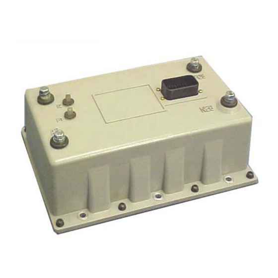
Page 9: Outline: Package Size
OUTLINE DRAWINGS, ELEMENTARY DRAWINGS AND INPUTS/OUTPUTS SX TRANSISTOR CONTROL Page 9 Section 3.2 Outline: Package Size Section 3.3 Standard Elementary for Neighborhood Electric Vehicle Application November 2012... -
Page 10: Standard Elementary For Neighborhood Electric Vehicle Application
OUTLINE DRAWINGS, ELEMENTARY DRAWINGS AND INPUTS/OUTPUTS SX TRANSISTOR CONTROL Page 10 FU3 * FU1 * Section 3.4 Neighborhood Electric Vehicle Application Input/Output List November 2012... -
Page 11: Standard Neighborhood Electric Vehicle Application Input/Output List
OUTLINE DRAWINGS, ELEMENTARY DRAWINGS AND INPUTS/OUTPUTS SX TRANSISTOR CONTROL Page 11 MAIN PLUG INPUT/OUTPUT DESCRIPTION BATTERY VOLTS FROM TOW SWITCH BATTERY VOLTS FROM TOW SWITCH BATTERY VOLTS FROM ACCELERATOR START SWITCH BATTERY VOLTS FROM FORWARD SWITCH BATTERY VOLTS FROM REVERSE SWITCH BATTERY VOLTS FROM KEY SWITCH ACCELERATOR INPUT VOLTAGE SIGNAL ACCELERATOR NEGATIVE... -
Page 12: Troubleshooting And Diagnostic Status Codes
FSIP does not recommend that any type of welding The following Do’s and Don’t’s should be be performed on the vehicle after the installation of the control(s) in the vehicle. -
Page 13: High Level Signals (Level H)
INSTALLATION AND OPERATION SX TRANSISTOR CONTROL Page 13 4.2.2.a Low-Level Signals (Level L) 4.2.2.d. High Power Signals (Level HP) Low-level signals are designated as level L. These Power wiring is designated as level HP. This consists consist of: of DC buses and motor wiring with currents greater ... -
Page 14: 4.2.5 Rf Interference
EV100/EV200 and Gen II products. 1. Disconnect plug from controller or mating plug. Any connection made by FSIP to the A, B, X, Y, or Z 2. Locate the plug that contains the socket (female) plugs, includes the lubricant NYE 760G to prevent terminals. -
Page 15: General Troubleshooting Instructions
Nye Lubricants NYOGEL 760G should be discharged by connecting a 200 ohm 2 watt resistor between the positive and negative FSIP Lube Kit Contains both above products: terminals on the control panel. 328A1777G1 Check resistance on R x 1000 scale from frame to Section 4.4 General Troubleshooting Instructions... -
Page 16: Traction Controller Status Codes
INSTALLATION AND OPERATION SX TRANSISTOR CONTROL Page 16 Section 4.5 Traction Control Codes TRACTION DESCRIPTION OF STATUS CAUSE OF STATUS INDICATION STATUS CODE Start switch fails to close. This status code will be displayed when the accelerator voltage at P7 is >1.4V, with the start switch open (P3 >... - Page 17 INSTALLATION AND OPERATION SX TRANSISTOR CONTROL Page 17 TRACTION DESCRIPTION OF STATUS CAUSE OF STATUS INDICATION STATUS CODE Accelerator voltage input is too high on This status code will be displayed when the power up after initial key switch accelerator input voltage at P7 >0.9V when the closure.
- Page 18 INSTALLATION AND OPERATION SX TRANSISTOR CONTROL Page 18 TRACTION DESCRIPTION OF STATUS CAUSE OF STATUS INDICATION STATUS CODE Start switch closed on power up after initial This status code will be displayed when P3 is key switch closure. less than 2.5 volts when the key switch is closed.
- Page 19 INSTALLATION AND OPERATION SX TRANSISTOR CONTROL Page 19 TRACTION DESCRIPTION OF STATUS CAUSE OF STATUS INDICATION STATUS CODE Battery voltage is too low at initial key This status code will be displayed when the switch closure. battery volts are less than 68.3 volts at initial key switch on.
- Page 20 INSTALLATION AND OPERATION SX TRANSISTOR CONTROL Page 20 TRACTION DESCRIPTION OF STATUS CAUSE OF STATUS INDICATION STATUS CODE Accelerator voltage is too high. This status code will be displayed when the accelerator voltage at P7 is greater than 4.5 volts. MEMORY RECALL CORRECTIVE ACTIONS TROUBLE-SHOOTING DIAGRAM...
- Page 21 INSTALLATION AND OPERATION SX TRANSISTOR CONTROL Page 21 TRACTION DESCRIPTION OF STATUS CAUSE OF STATUS INDICATION STATUS CODE Motor field current is too high when the This status code will be displayed when the current key switch is turned on. draw in the motor field is too high on start up.
- Page 22 INSTALLATION AND OPERATION SX TRANSISTOR CONTROL Page 22 TRACTION DESCRIPTION OF STATUS CAUSE OF STATUS INDICATION STATUS CODE Shorted thermal protector (TP) or This status code will be displayed when the voltage at transistor over temperature. the thermal protector is too low. MEMORY RECALL CORRECTIVE ACTIONS TROUBLE-SHOOTING DIAGRAM...
- Page 23 INSTALLATION AND OPERATION SX TRANSISTOR CONTROL Page 23 TRACTION DESCRIPTION OF STATUS CAUSE OF STATUS INDICATION STATUS CODE Motor armature offset voltage is too This status code will be displayed when the value of low. motor amps is less than 123 (corresponding to 2.4 volts) with no current flowing in the motor circuit.
- Page 24 INSTALLATION AND OPERATION SX TRANSISTOR CONTROL Page 24 TRACTION DESCRIPTION OF STATUS CAUSE OF STATUS INDICATION STATUS CODE Armature transistor did not turn on This status code will be displayed when, during properly. control operation, the armature transistor fails to turn on properly.
- Page 25 INSTALLATION AND OPERATION SX TRANSISTOR CONTROL Page 25 TRACTION DESCRIPTION OF STATUS CAUSE OF STATUS INDICATION STATUS CODE Motor field current is too low during the This status code will be displayed when the current run mode. draw in the motor field is less than 1.3 amps and armature current is greater than 100 amps for more than 1.27 seconds during the run mode.
- Page 26 INSTALLATION AND OPERATION SX TRANSISTOR CONTROL Page 26 TRACTION DESCRIPTION OF STATUS CAUSE OF STATUS INDICATION STATUS CODE Controller “motor current sensor” input This status code will be displayed when the voltage is too low during running. input from the current sensor is too low (less than 1.0V, 416 amps) during running.
- Page 27 INSTALLATION AND OPERATION SX TRANSISTOR CONTROL Page 27 TRACTION DESCRIPTION OF CAUSE OF STATUS INDICATION STATUS CODE STATUS The line coil current is too high This status code will be displayed when the current limit in during the run mode the line coil is exceeded during the run mode.
- Page 28 INSTALLATION AND OPERATION SX TRANSISTOR CONTROL Page 28 TRACTION DESCRIPTION OF STATUS CAUSE OF STATUS INDICATION STATUS CODE Capacitor (1C) voltage too high during This status code will be displayed when the voltage at pedal up regen braking. 1C exceeds 96 volts during the regenerative braking cycle.
- Page 29 INSTALLATION AND OPERATION SX TRANSISTOR CONTROL Page 29 TRACTION DESCRIPTION OF STATUS CAUSE OF STATUS INDICATION STATUS CODE No tachometer signal is detected. This status code will be displayed when no tachometer signal is detected. MEMORY RECALL CORRECTIVE ACTIONS TROUBLE-SHOOTING DIAGRAM SYMPTOM +72V +72V...
-
Page 30: Set Up Functions For Traction Controller
Palm, Inc, the Palm logo and Palm be determined by FSIP and OEM engineers at the Powered logo are the trademarks of Palm, Inc. time of vehicle development. This setting must not be... - Page 31 Setting of 73 = (73-51) * 0.15 motor and control performance and this setting will = 3.3 amps be determined by FSIP and OEM engineers at the time of vehicle development. This setting must not be CAUTION: Do not set this function to a value less changed by field personnel without the permission of than 51.
- Page 32 FUNCTION 15 Battery Volts motor and control performance and this setting will be determined by FSIP and OEM engineers at the In order for the battery discharge indication feature of time of vehicle development. This setting must not be this control to operate properly, this function must be changed by field personnel without the permission of set to a value between 70 and 80.
- Page 33 Example Setting of 60 = 60 * 0.5 be determined by FSIP and OEM engineers at the = 30 minutes time of vehicle development. This setting must not be changed by field personnel without the permission of FUNCTION 28 Stored Status Code Pointer the OEM.
-
Page 34: Memory Map
RS-232 MEMORY MAP TABLES SX TRANSISTOR CONTROL Page 34 Section 6.0 MEMORY MAP Func Traction Control Function Access By Restrictions MPH Scaling PC or PDA None Creep Speed PC or PDA None Armature Acceleration Rate PC or PDA None Max Armature Current Limit PC or PDA None Plug Current Limit... - Page 35 RS-232 MEMORY MAP TABLES SX TRANSISTOR CONTROL Page 35 Func Traction Control Function Access By Restrictions BDI 4 PC or PDA Reset to Zero Only Hours (Tens/Ones) 4 PC or PDA Reset to Zero Only Hours (Thou/Hun) 4 PC or PDA Reset to Zero Only Stored Status Code #5 PC or PDA...
- Page 36 RS-232 MEMORY MAP TABLES SX TRANSISTOR CONTROL Page 36 Hours (Thou/Hun) 15 PC or PDA Reset to Zero Only Func Traction Control Function Access By Restrictions Stored Status Code #16 PC or PDA Reset to Zero Only Hours (Tens/Ones) 16 PC or PDA Reset to Zero Only Hours (Thou/Hun) 16...
Need help?
Do you have a question about the IC3645SR4A403E1 and is the answer not in the manual?
Questions and answers