
Related Manuals for EpiSensor ZMB-30


Summary of Contents for EpiSensor ZMB-30
- Page 1 User Guide Wireless Modbus Interface Applies to: ZMB-30, ZMB-31, ZMB-33 EPI-194-00 © EpiSensor...
-
Page 2: Table Of Contents
Table of Contents Safety Information Electrical Installation Intended Use Related Documents Introduction User Interface Status LED Alt LED Mode Button Install Mode Electrical Installation Mechanical Enclosure & Label Material Mounting Instructions Opening the Enclosure Tamper Evident Seals Compliance Communications Configuration Wireless Communications Sensors Reading Data... -
Page 3: Safety Information
Only qualified electrical workers should install this equipment. Such work should be performed only after reading the entire set of installation instructions. ➔ If the equipment is not used in a manner specified by EpiSensor, the protection provided by the equipment may be impaired. Page 3 of 19... - Page 4 Installation & Safety Notes ➔ EpiSensor equipment should be installed, operated, serviced and maintained only by qualified personnel. EpiSensor does not assume any responsibility for any consequences arising out of the use of this equipment. ➔ Fuse for neutral terminal is required if the source neutral connection is not grounded.
-
Page 5: Intended Use
Related Documents Related installation and configuration documents are listed in the following table: Document Reference No. EPI-195-00 EpiSensor ZMB Datasheet EPI-090-00 Install Sheet for ZMB-3X EPI-143-00 Application Note - ZMB Device Compatibility EPI-104-00 Application Note - Modifying Node Profiles for ZMB Product Range... -
Page 6: Introduction
Introduction EpiSensor’s ZMB Wireless Modbus Interface is designed to make it easy to collect data from a wide range of heating, cooling and other energy meters using the Modbus RTU (over RS-485) wired communications standard. The ZMB reports data through the wireless sensor network to the Gateway, which then manages bi-directional communications to various compatible software and IoT platforms. -
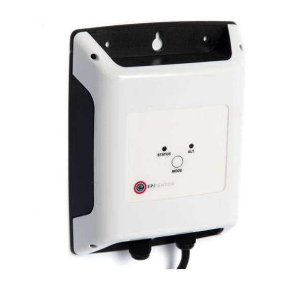
Page 7: Alt Led
Check the power supply, and if the problem persists, contact EpiSensor support. Alt LED The Alt LED will flash when data is transmitted or received on the ZigBee wireless network. For mains powered nodes, it will always be active - but for battery powered nodes, it will only be active when in Command Mode. -
Page 8: Install Mode
Send a DATA message to the Gateway for any enabled sensors that are not reporting in ‘snap-to-clock’ mode. Leave the current network. Mains powered Nodes will automatically try and join a new network once they have left and will periodically retry the join. Battery powered nodes will go to sleep. Start “Install Mode”. -
Page 9: Mechanical
Installation should only be carried out only by personnel qualified in the installation of electrical equipment. All parts of the circuit within the enclosure must be considered to be at dangerously high mains voltage when the unit is connected to a mains voltage source. Mechanical This section describes how to wall-mount the ZMB enclosure, the enclosure materials and important safety considerations when connecting the ZMB to external systems. -
Page 10: Opening The Enclosure
ZMB has been isolated from any high voltage supplies. Please consult the safety notes at the start of this user guide for more information. Important Safety Note EpiSensor equipment should be installed, operated, serviced and maintained only by qualified personnel. There are no user-serviceable parts inside the ZMB enclosure, and it should always be isolated from mains voltages before opening the enclosure lid. -
Page 11: Compliance
The label material is gloss white PVC foil with permanent adhesive and gloss overlaminate. The following table lists the certification and safety symbols that appear on the certification labels of EpiSensor products. Please refer to it for a definition of each symbol. -
Page 12: Communications
Communications There are a variety of communication options on the ZMB that are used to configure settings, stream live sensor data and poll 3rd party systems for data. This section describes the communications capability of the ZMB, with information on wiring, configuration and safety considerations. Modbus communications are possible from the ZMB using an RS485 multidrop network or an RS232 point to point cable running at TTL levels (3.3Volts). -
Page 13: Configuration
the greater the attenuation. Because attenuation increases with frequency, cables also exhibit a lowpass filter behavior so that achievable distance diminishes with data rate. The communications parameters are configured using the Gateway UI or the API. Because Modbus is the only protocol implemented on the RS485 network, and Modbus always uses 8 data bits, the number of databits are not configurable. - Page 14 communications parameters - those being the Baud Rate, Parity and Stop Bits. All Modbus devices must use 8 databits (if it is configurable). Property ID Setting Description Unit Resolution Reporting Default Read/Write 6410 Modbus Baud Rate RS485 Communication Parameter for Read/Write Modbus Network 6411...
-
Page 15: Wireless Communications
Note: Error codes from Modbus are detected by the ZMB but are currently not reported to the Gateway. Wireless Communications All EpiSensor products use IEEE 802.15.4 ZigBee Pro for wireless communications operating at 2.4GHz. This is a secure, scalable mesh networking communications protocol designed for transmitting small amounts of data reliably, and at low power levels. -
Page 16: Sensors
1600m (5250ft) North America (FCC / IC) All communications over the ZigBee wireless network is AES 128-bit encrypted. For more detailed information on ZigBee security features, contact EpiSensor support. Sensors Reading Data The ZMB reads data by polling each of the Modbus Sensors that have become due to report. The ZMB builds a “Read Data”... -
Page 17: Ordering Information
Additionally, the following sensor is available on ZMB’s that are supplied with a temperature probe: Sensor ID Data Feed Description Unit Resolution Reporting Default Read/Write Temperature Temperature Sensor 0.01C 15min Read/Write Page 17 of 19... -
Page 18: Glossary
Mains powered, no temperature probes, max 4 Modbus registers, live stream mode Troubleshooting & Support If you are experiencing problems with your ZMB or any other part of your EpiSensor system, or you notice something unusual - please contact EpiSensor support at the following email address, phone number or via live chat on our website. - Page 19 ZigBee IEEE 802.15.4 Wireless communications standard that EpiSensor nodes use Wireless Sensor Network Reporting Mode Defines how an EpiSensor node should report data to the Gateway Reporting The length of time between each data point produced by a node Interval Reporting mode where data is ‘snapped’...
Need help?
Do you have a question about the ZMB-30 and is the answer not in the manual?
Questions and answers