Table of Contents
Advertisement
Quick Links
Advertisement
Table of Contents

Related Manuals for Servo Dynamics 1224-BL

Summary of Contents for Servo Dynamics 1224-BL
- Page 1 1224-BL SERVO AMPLIFIER FOR BRUSHLESS SERVOMOTORS USER GUIDE October 2004...
- Page 2 Important Notice This document is subject to the following conditions and restrictions: • This document contains proprietary information belonging to Servo Dynamics. This information is provided for the purpose of assisting users of the servo drive in its installation. • The text and graphics in this document are for the purpose of illustration and reference only.
-
Page 3: Table Of Contents
J4 and J2 - Servomotor Connection ..................10 Wiring Diagram ......................11 3.4.1 DynaDrive 1224-BL and Motor with Hall Sensors............... 11 3.4.2 DynaDrive 1224-BL and Motor with Encoder with Hall Tracks.......... 12 Potentiometers -Adjustments ..................13 Operational Modes......................14 Torque Mode......................... 14 4.1.1 Torque Mode –... -
Page 4: Introduction
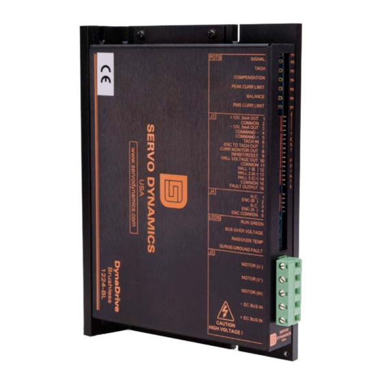
(torque and velocity) and troubleshooting procedures for the brushless DynaDrive 1224-BL. Description The DynaDrive 1224-BL supplies 12 amps continuous current and 24 amps peak current at 300 VDC for a total of 7200 watts of continuous power. The DynaDrive is a current source type PWM amplifier. -
Page 5: Technical Specifications
7.6 in. x 1.3 in. x 5.4 in. Weight 1.8 lbs Ambient Temperature – Operating 0 °C to 50 °C Shutdown Temperature 80 °C at heat sink Relative Humidity 5 - 95% non-condensing Table 1: Technical Specifications for DynaDrive 1224-BL DynaDrive 1224-BL User Guide Page... -
Page 6: Safety Information
Safety Information 2. Safety Information Electrical Cautions Make sure that all voltages and tests are made with battery powered or electrically isolated instruments. DynaDrive 1224-BL User Guide Page... -
Page 7: Installation
3. Installation Matching the DynaDrive to the Motor The factory preset potentiometer settings of the DynaDrive 1224-BL may need to be adjusted to match the continuous current rating of your motor. To accomplish this, find the continuous current rating of the motor to be used and adjust the RMS, PEAK CURR LIMIT and SIGNAL pot per below. -
Page 8: Mounting Dimensions
Installation Mounting Dimensions Note: Units in inch DynaDrive 1224-BL User Guide Page... -
Page 9: Connector Information
Uncommitted collector output that is high (On) during normal FAULT OUTPUT operation and low (Off) if a fault occurs. Note: Use an external pull up resistor to 5 – 24 Vdc at 10 mA max. DynaDrive 1224-BL User Guide Page... -
Page 10: J4 And J2 - Servomotor Connection
Enc. Common Encode Ground Label Description MOTOR(U) Output power to motor MOTOR(V) Output power to motor MOTOR(W) Output power to motor - DC BUS IN DC Bus Return + DC BUS IN DC Bus High Side DynaDrive 1224-BL User Guide Page... -
Page 11: Wiring Diagram
Installation Wiring Diagram 3.4.1 DynaDrive 1224-BL and Motor with Hall Sensors J1 CONNECTOR PIN 1 12 V, 5mA OUT PIN 2 COMMON PIN 3 12 V, 5mA OUT PIN 4 COMMAND PIN 5 COMMAND PIN 6 TACH IN 150-260 VAC... -
Page 12: Dynadrive 1224-Bl And Motor With Encoder With Hall Tracks
Installation 3.4.2 DynaDrive 1224-BL and Motor with Encoder with Hall Tracks J1 CONNECTOR PIN 1 12 V, 5mA OUT PIN 2 COMMON PIN 3 12 V, 5mA OUT PIN 4 COMMAND PIN 5 COMMAND 150-260 VAC BLEEDER PIN 6 TACH IN... -
Page 13: Potentiometers -Adjustments
The RMS potentiometer is for changing the level of the RMS current. The amplifier is capable of providing maximum RMS current when fully CW. The minimum current is approximately 0 amps when fully CCW. DynaDrive 1224-BL User Guide Page... -
Page 14: Operational Modes
Torque Mode 4.1.1 Torque Mode – Factory Potentiometer Settings The DynaDrive 1224-BL is shipped in the torque mode by installing the torque mode jumper at J3 and presetting the potentiometers for the torque mode. The factory potentiometer settings for the torque mode are as follows: (See ADJUSTMENTS section for a more complete description... -
Page 15: Torque Mode - Setup
Operational Modes 4.1.2 Torque Mode - Setup The factory preset potentiometer settings are adjusted for the torque mode operation. To set up and run the DynaDrive 1224-BL in the torque mode, perform the following: 1. Turn power off. 2. Remove J1. -
Page 16: Velocity Mode
The Velocity mode Table 3 requires a tachometer feedback signal from the motor or motion control system. To match the motor to the DynaDrive 1224-BL, set the RMS and SIGNAL pots per . Set Table 2 the PEAK CURR LIMIT pot to full CCW. Set the remaining pots per Table below. -
Page 17: Velocity Mode- Setup
Operational Modes 4.2.2 Velocity Mode- Setup To set up and run the DynaDrive 1224-BL in the Velocity mode, perform the following: 1. Turn power off. 2. Remove J1. 3. Check all wiring connections. Verify that J3 jumper is removed. 4. Check that the pots are set per Table 3. -
Page 18: Troubleshooting
Troubleshooting 5. Troubleshooting Diagnostic LEDs The DynaDrive 1224-BL has four diagnostic LEDs: 1) RUN GREEN 2) BUS OVER VOLTAGE 3) RMS/ OVER TEMP 4) SURGE/ GROUND FAULT 5.1.1 Green LED RUN GREEN - Indicates the amplifier is working properly. When the green LED goes OFF and there is no red LEDs ON, the following may have occurred: 1. -
Page 19: Other Conditions
VARIOUS SHAFT 2. Check the wires from the motor commutator sensors and make POSITIONS sure the motor commutator signals are making connection in J1, Pins 12, 13 and 14 on the connector on the amplifier module. DynaDrive 1224-BL User Guide Page... -
Page 20: Test Points
TACH input wiper COMPENSATION POT wiper PEAK CURR LIMIT POT wiper TACH IN signal directly connected to J1, pin 6 thru a 10K resistor RMS current setting pot wiper Front-end opamp output (J3, pin 2) DynaDrive 1224-BL User Guide Page... -
Page 21: Contact Information
Troubleshooting Contact Information If you are unable to resolve the problem, consult our web page located at: http://www.servodynamics.com/ Contact the service department at Servo Dynamics: Servo Dynamics 21541 Nordhoff Street Chatsworth, CA 91311 U.S.A. Tel: +1 (818) 700 8600 Fax: +1 (818) 718 6719...
Need help?
Do you have a question about the 1224-BL and is the answer not in the manual?
Questions and answers