Table of Contents
Advertisement
Quick Links
Instruction Manual for
SEPAREL EF Modules
Before using the SEPAREL® EF series, be sure to read this instruction manual to ensure safe and
proper use.
DIC will not have any liability to a customer or end user in connection with any costs and damages
arising directly or indirectly from any defective modules.
We are not responsible for any usage, installation, or any other handling done by the customer.
The module must be used, installed, and handled responsibly by the customer.
Application Materials Product Division
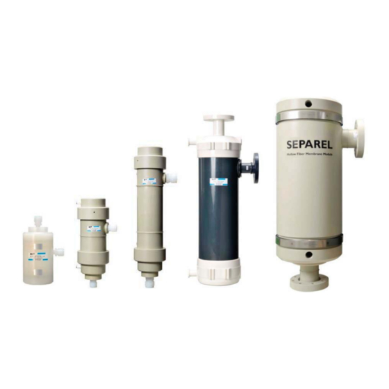
Hollow Fiber Membrane Module
EF (External Flow) Series
EF-002A Series
EF-010 Series
EF-020 Series
EF-040P Series
EF-120 Series
EF-002A-P
EF-010
EF-020
EF-040P
Ver. 1. 2
June
3, 2016
EF-120
www.separel.com/en
Advertisement
Table of Contents

Summary of Contents for SEPAREL EF Series
- Page 1 EF-040P EF-120 Before using the SEPAREL® EF series, be sure to read this instruction manual to ensure safe and proper use. DIC will not have any liability to a customer or end user in connection with any costs and damages arising directly or indirectly from any defective modules.
- Page 2 EF-002A, EF-010, EF-020, and EF-120 series, with precautions to be followed for your safety. Before using the SEPAREL® EF series, be sure to read this instruction manual to ensure safe and proper use. Depending on use conditions, proper methods for usage and storage may differ even though there are descriptions about usage methods, storage methods, and risks associated with the product module within this manual.
- Page 3 INSTRUCTION MANUAL Warranty, Warranty Period Warranty At the time of delivery, DIC warrants that the Separel module will be free from defects in material and workmanship and meet the specifications supplied to the customer by DIC. Warranty Period The following Warranty Period is applied only if customer use of the Separel module is in accordance with the instructions contained in this manual, the specification sheet, any applicable Cleaning Guides and the Warranty Statement.
- Page 4 INSTRUCTION MANUAL Warranty Remedy Warranty Remedy During the applicable warranty period as specified in the Warranty Statement, any defective module will be replaced free of charge by DIC in cases where a defect is found under normal use in accordance with this instruction manual and under use and storage conditions specified in the specification sheet and Warranty Statement.
-
Page 5: Table Of Contents
INSTRUCTION MANUAL Contents 1. General Precautions P. 6 2. Upon Receipt P. 6 3. Installation P. 7 4. Start-Up P. 13 5. Shutoff and Storage P. 15 6. Restart P. 15 7. Maintenance P. 16 Reference Data 1. Basic Principles of Degassing P.17 2. -
Page 6: General Precautions
1-4. Do not feed the following liquids into SEPAREL–oxidizing agents (highly concentrated chlorine water, ozone water, etc.), strong acids, strong bases, organic solvents, alcohol, oils, or any other liquid which is not compatible with the liquid and materials that SEPAREL modules are composed of. -
Page 7: Installation
INSTRUCTION MANUAL 3. Installation Type of SEPREL EF-Series Modules Application Materials Product Division... - Page 8 INSTRUCTION MANUAL 3. Installation Degasification Methods (1) Vacuum Mode Vacuum Mode is an effective method to remove gases from liquids using the two vacuum ports. This process is when vacuum drawing occurs with a pump that is inside the hollow fiber. Vacuum drawing lowers the partial pressure on the lumen side, making the dissolved gas move to the shell side.
- Page 9 Example of Installation It is possible particles may be present and pass through the module. If there is any trouble with such particles, please install a filter and filter the liquids after they exit the SEPAREL module, but before application.
- Page 10 Set the vacuum port downward to smoothly purge liquid derived from vapor. If you fix SEPAREL with a U-band, make sure not to loosen the fitting. Do not apply too much pressure when fixing SEPAREL with a U-band as too much pressure may damage the module.
- Page 11 If impurities and large particles remain in liquid, install a filter in front of the SEPAREL module. Use RO water or higher quality water for the water supply. In the event water of a water quality lower than RO water is used: Please ensure the remaining chloride concentration is, 1mg/L".
- Page 12 3. Installation 2) Liquid Out: There is a possibility that particles are generated by the SEPAREL module. To prevent a problem with such particle occurrence, install a filter behind the module. The most suitable filtration size depends on your use conditions. For more details, please contact DIC.
-
Page 13: Start-Up
For efficient removal of remaining air in the liquid area of SEPAREL modules, filling the liquid with a vacuum is recommended. During the vacuuming process, check the airtightness of the vacuum line and not the air that is leaked from pipe, connector, and SEPAREL module. - Page 14 INSTRUCTION MANUAL 4. Start-Up Start-up Procedure for each operating mode Vacuum Mode (1) Start up the vacuum pump in accordance with the specifications prepared by the vacuum pump manufacturer: (2) Perform vacuum pumping of the module. (3) Adjust the pressure on the vacuum pumping side to the specified value. Sweep Mode (1) Set the flow volume in accordance with the specified value (2) If there is purified water inside the in the vacuum side’s hollow fiber, purge it with sweep gas.
-
Page 15: Shutoff And Storage
INSTRUCTION MANUAL 5. Shutoff and Storage 5-1. Shutdown Procedure (1) Open the leak valve of the vacuum exhaust pipe. Upon confirming that the vacuum has been released, shut down the vacuum pump. (2) Close the valve on the liquid supply side then close the valve on the treated liquid side. 5-2. -
Page 16: Maintenance
It is necessary to have regular checkups to maintain the performance of the degasification module. Check the items described in the following table and record the results. Frequency Items of Measure Guideline for Set Value Item to Check Measurement More than once a Water Supply Value Design value Make sure that it does not exceed the maximum water... -
Page 17: Basic Principles Of Degassing
INSTRUCTION MANUAL REFRENCE DATA 1: Basic Principles of Degassing Sealing Resin Image of Hollow Fiber Cross-section Liquid Liquid Liquid Hollow Fibers Hollow Fiber Hollow Fiber Membrane Membrane Sealing Resin Inside of Hollow Fiber for Vacuuming By vacuuming inside the hollow fiber, only gas can pass through hollow fiber membrane and is removed from liquid. -
Page 18: Vacuum Pressure Degree
INSTRUCTION MANUAL REFRENCE DATA 2: Vacuum Pressure Degree Note that the vacuum pressure degree in our data sheet is mainly indicated by absolute pressure, not by gauge pressure. 1 atm 0.65 atm 0.35 atm Absolute =101.3 kPa(abs) = 65.8 kPa(abs) = 35.5 kPa(abs) = 1013 mbar(abs) = 658 mbar(abs) -
Page 19: Setting Value Of Vacuum Pressure Degree
INSTRUCTION MANUAL REFRENCE DATA 3: Setting Value of Vacuum Pressure Degree As the vacuum pressure degree approaches a perfect vacuum, degassing performance is improved. However, if the vacuum pressure degree is too strong yet close to perfect pressure, liquid may evaporate and penetrate through the membrane. - Page 20 INSTRUCTION MANUAL REFRENCE DATA 4: Setting Value of Vacuum Pressure Degree Make sure that the liquid feeding pressure at the inlet port is lower than the maximum pressure value described in the specification sheet. If the feeding pressure exceeds the maximum value, even momentarily, the hollow fiber may be damaged and ink may leak into the vacuum line.
-
Page 21: Inner Volume
INSTRUCTION MANUAL REFRENCE DATA 5: Inner Volume Approx. Approx. Approx. Approx. Approx. Approx. The above values are for reference and are not guaranteed values. Actual volume may differ by connection type. Application Materials Product Division... -
Page 22: Troubleshooting
INSTRUCTION MANUAL REFRENCE DATA 6: Troubleshooting Problems Probable Causes How to Solve the Problem Dissolved gas Stains on the Cleansing of degasification module (refer to the Cleansing concentration degasification module. Guidelines). is higher than The dust cover during Confirm that the dust plug for transportation is removed from specified or transportation is not removed. - Page 23 INSTRUCTION MANUAL REFRENCE DATA 6: Troubleshooting Problems Probable Cause How to Solve the Problem Dissolved gas Condensation inside the If the degasification module is still wet at shutdown, there concentration is degasification module or vacuum line. is a possibility that flocculation of water is happening on the higher than shell side (inside the hollow fiber).
- Page 24 INSTRUCTION MANUAL REFRENCE DATA 6: Troubleshooting Problems Probable Cause How to Solve the Problem Pressure loss is The dust cover for transportation is Confirm that the dust cover/end cap plug is removed. significant on the not removed. lumen side. Accumulation of minute particles on Check the filter system.
Need help?
Do you have a question about the EF Series and is the answer not in the manual?
Questions and answers