Table of Contents
Advertisement
Available languages
Available languages
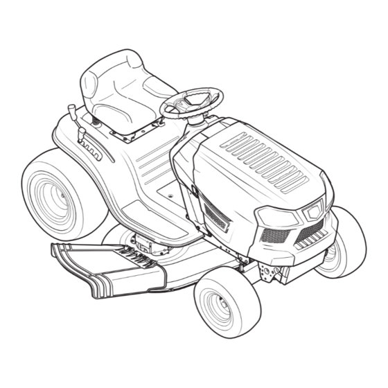
Operator's Manual
T1000 LAWN TRACTOR
7 Speed, Shift-on-the-Go
42" Deck
Model No. 247.203702
• Espanol, P. 32
This product has a low emission engine which operates differently
from previously built engines. Before you start the engine, read and
understand this Operator's Manual.
CAUTION
Before using this equipment,
read this manual and follow
all safety rules and operating
instructions.
Sears Brands Management Corporation, Hoffman Estates, IL 60179 U.S.A.
Visit our website: www.craftsman.com
For answers to your questions about
this product, call:
1-888-331-4569
Craftsman Tractor Help Line
7 am - 7 pm CT, Mon. - Sun.
Form No. 769-09446B
(November 3, 2014)
Advertisement
Chapters
Table of Contents

Related Manuals for Craftsman 247.203702


Summary of Contents for Craftsman 247.203702
- Page 1 Operator’s Manual T1000 LAWN TRACTOR 7 Speed, Shift-on-the-Go 42” Deck Model No. 247.203702 • Espanol, P. 32 This product has a low emission engine which operates differently from previously built engines. Before you start the engine, read and understand this Operator’s Manual.
-
Page 2: Table Of Contents
WARRANTY SERVICE For warranty coverage details to obtain free repair or replacement, call 1-888-331-4569 or visit the web page: www.craftsman.com/warranty In all cases above, if part repair or replacement is impossible, the riding equipment will be replaced free of charge with the same or an equivalent model. -
Page 3: Safety Instructions
SAFETY INSTRUCTIONS WARNING DANGER This symbol points out important safety instructions which, if not This machine was built to be operated according to the safe operation followed, could endanger the personal safety and/or property of practices in this manual. As with any type of power equipment, yourself and others. - Page 4 SAFETY INSTRUCTIONS Do Not: • Check overhead clearances carefully before driving under low hanging tree branches, wires, door openings etc., where the operator may be struck or • Do not turn on slopes unless necessary; then, turn slowly and gradually pulled from the machine, which could result in serious injury.
- Page 5 SAFETY INSTRUCTIONS • On slopes, the weight of the towed equipment may cause loss of traction and • Periodically check to make sure the blades come to complete stop within loss of control. approximately (5) five seconds after operating the blade disengagement control.
- Page 6 SAFETY INSTRUCTIONS DO NOT MODIFY ENGINE SPARK ARRESTOR To avoid serious injury or death, do not modify engine in any way. Tampering WARNING with the governor setting can lead to a runaway engine and cause it to operate at unsafe speeds. Never tamper with factory setting of engine This machine is equipped with an internal combustion engine and should governor.
- Page 7 SAFETY INSTRUCTIONS Symbol Description DANGER — SAFETY DEVICES Keep safety devices (guards, shields, switches, etc . ) in place and working . BYSTANDERS Keep bystanders, helpers, children and pets at least 75 feet from the machine while it is in operation .
-
Page 8: Slope Gauge
SLOPE GAUGE... -
Page 9: Assembly
ASSEMBLY IMPORTANT: Your tractor is shipped with motor oil in the engine. However, Shipping Brace Removal you MUST check the oil level before operating. Refer to the Service & Maintenance WARNING section for instructions on checking the oil level. Make sure the riding mower’s engine is off, remove the ignition key, and Attaching the Battery Cables set the parking brake before removing the shipping brace. - Page 10 ASSEMBLY Slide the seat rearward in the seat pivot bracket (c), lining up the center rear slot in the pivot bracket with the remaining hole in the seat’s base. See Figure 5. Note: Be certain the two seat tabs engauge the pivot bracket as shown in the bottom inset of Figure 5.
-
Page 11: Operation
NOTE: Any reference in this manual to the RIGHT or LEFT side of the tractor is observed from operator’s seat position facing forward towards the front of tractor. Meets ANSI Safety Standards Craftsman Tractors conform to the safety standard of the American National Standards Institute (ANSI). - Page 12 OPERATION Speed Control Lever Shift Lever The speed control lever, located on the left side of the tractor’s The shift lever is located on the left side dash console, allows you to regulate the ground speed of the lawn of the fender and has three positions, tractor.
- Page 13 OPERATION Gas and Oil Fill-up IMPORTANT: Your tractor is shipped with motor oil in the engine. However, you MUST check the oil level before operating. Be careful not to overfill. For instructions on how to check the engine oil, refer to Checking The Engine Oil in the Service and Maintenance section of this manual.
- Page 14 OPERATION Setting the Cutting Height • The engine will automatically shut off if the PTO (Blade Engage) lever is moved into the engaged (ON) position with the shift lever in Reverse. Select the height position of the cutting deck by placing the deck lift lever in Ignition Switch any of the six different cutting height notches on the right side of the fender.
- Page 15 OPERATION Stopping the Engine Engage the parking brake. Shut engine off and remove the key. Doing so will minimize the possibility WARNING of having your lawn ‘‘browned’’ by hot exhaust from your tractor’s running If you strike a foreign object, stop the engine, disconnect the spark engine.
- Page 16 OPERATION Mulching Headlights A mulch kit is available as an attachment. Mulching is a process of recirculating • The lamps are ON whenever the tractor’s engine is running. grass clippings repeatedly beneath the cutting deck. The ultra-fine clippings are • The lamps turn OFF when the ignition key is moved to the STOP position.
-
Page 17: Service And Maintenance
SERVICE AND MAINTENANCE MAINTENANCE SCHEDULE WARNING Before performing any type of maintenance/service, disengage all controls Follow the maintenance schedule given below. This chart describes service and stop the engine. Wait until all moving parts have come to a complete guidelines only. Use the Service Log column to keep track of completed stop. - Page 18 SERVICE AND MAINTENANCE Engine Maintenance Changing the Engine Oil and Filter Checking the Engine Oil WARNING Use a 4-stroke, or an equivalent high detergent, premium quality motor oil certified to If the engine has been recently run, the engine, muffler and surrounding meet or exceed U.S.
- Page 19 SERVICE AND MAINTENANCE • Before replacing the fuel filter, drain the fuel tank. Otherwise, fuel can leak out and cause a fire or explosion. To Drain the fuel: Locate the fuel filter, see Figure 12, which is routed on the left side of the engine between the fuel tank and the carburetor, and may be attached to the engine with a tie strap.
- Page 20 SERVICE AND MAINTENANCE Air Filter Remove the foam pre-filter from around the paper air filter. See Figure 15. Replace paper element when dirty or damaged. Clean foam element or Paper filters cannot be cleaned and should be replaced every 100 operating hours; replace when damaged.
- Page 21 SERVICE AND MAINTENANCE Attach the air filter cover, making sure to align plastic rib features on the Measure the plug gap with a feeler gauge. Correct as necessary by bending shroud to the plastic features on the air filter cover. See Figure 17. Turn side electrode.
- Page 22 SERVICE AND MAINTENANCE Lubrication IMPORTANT: The use of a pressure washer to clean your tractor is NOT recommended. It may cause damage to electrical components, spindles, pulleys, WARNING bearings or the engine. Before lubricating, repairing, or inspecting, always disengage PTO (Blade Adjustments Engage Lever), move shift lever into neutral position, set parking brake, stop WARNING...
- Page 23 SERVICE AND MAINTENANCE Cutting Deck Removal Side to Side To remove the cutting deck, proceed as follows: If the cutting deck appears to be mowing unevenly, a side to side adjustment can be performed. Adjust if necessary as follows: Place the PTO (Blade Engage) lever in the disengaged (OFF) position and With the tractor parked on a firm, level surface, place the deck lift lever in engage the parking brake.
- Page 24 SERVICE AND MAINTENANCE PTO Cable Bow-Tie Clip Figure 23 Figure 25 Remove the bow-tie cotter pin securing the deck stabilizer rod to the deck. Tires Slide the deck lift rod from the mounting bracket on the deck as shown in Figure 24.
- Page 25 SERVICE AND MAINTENANCE Connect the second cable (negative –) to the other post of the jumper Remove the deck from beneath the tractor, (refer to Cutting Deck Removal battery. earlier in this section) then gently flip the deck over to expose its underside. Connect the other end of the negative cable to the engine block of the Place a block of wood between the center deck housing baffle and the tractor, away from the battery.
- Page 26 SERVICE AND MAINTENANCE NOTE: When replacing the blade, be sure to install the blade with the side of the Then route the belt around the two deck idler pulleys as shown in Figure 28. blade marked ‘‘Bottom’’ (or with a part number stamped in it) facing the ground Retighten the belt keeper rod loosened earlier.
-
Page 27: Off-Season Storage
OFF-SEASON STORAGE WARNING Never store lawn tractor with fuel in tank indoors or in poorly ventilated areas where fuel fumes may reach an open flame, spark, or pilot light as on a furnace, water heater, clothes dryer, or gas appliance. Preparing The Engine Draining The Fuel IMPORTANT: Fuel left in the fuel tank during warm weather deteriorates and... -
Page 28: Troubleshooting
TROUBLESHOOTING Problem Cause Remedy Engine fails to start PTO/Blade Engage lever engaged. Place lever in disengaged (OFF) position. Parking brake not engaged. Engage parking brake. Spark plug wire(s) disconnected. Connect wire(s) to spark plug(s). Throttle/Choke control lever not in correct Place Throttle/Choke lever into the FAST position. - Page 29 FEDERAL and/or CALIFORNIA EMISSION CONTROL WARRANTY STATEMENT YOUR WARRANTY RIGHTS AND OBLIGATIONS MTD Consumer Group Inc, the United States Environmental Protection Agency (EPA), and for those products certified for sale in the state of California, the California Air Resources Board (CARB) are pleased to explain the evaporative emission control system (ECS) warranty on your 2014-2015 small off-road equipment (outdoor equipment) .
- Page 30 WARRANTED PARTS: The repair or replacement of any warranted part otherwise eligible for warranty coverage may be excluded from such warranty coverage if MTD Consumer Group Inc demonstrates that the outdoor equipment has been abused, neglected, or improperly maintained, and that such abuse, neglect, or improper maintenance was the direct cause of the need for repair or replacement of the part .
- Page 31 REPAIR PROTECTION AGREEMENT Congratulations on making a smart purchase. Your new Craftsman® product is designed and manufactured for years of dependable operation. But like all products, it may require repair from time to time. That’s when having a Repair Protection Agreement can save you money and aggravation.
-
Page 32: Español
SERVICIO DE GARANTÍA Para detalles de la cobertura de garantía para obtener la reparación o sustitución gratuita, llame al 1-888-331-4569 o visite la página Web: www.craftsman.com/warranty En todos los casos anteriores, si es imposible la reparación o el reemplazo parte, será sustituido de forma gratuita el equipo de montar a caballo con el mismo o un modelo equivalente. -
Page 33: Operación Segura Prácticas
INSTRUCCIONES DE SEGURIDAD ADVERTENCIA PELIGRO Esta máquina fue construida para ser operada de acuerdo con La presencia de este símbolo indica que se trata de instrucciones las reglas de seguridad contenidas en este manual. Al igual que importantes de seguridad que se deben respetar para evitar con cualquier tipo de equipo motorizado, un descuido o error por poner en peligro su seguridad personal y/o material y la de otras parte del operador puede producir lesiones graves. - Page 34 INSTRUCCIONES DE SEGURIDAD • Nunca deje la máquina en funcionamiento sin vigilancia. Apague • Tenga especial cuidado con los colectores de césped u otros siempre las cuchillas, coloque el freno de mano, detenga el motor y aditamentos. Los mismos pueden modificar la estabilidad de la retire la llave antes de bajarse del vehículo.
- Page 35 INSTRUCCIONES DE SEGURIDAD No permita nunca que los niños menores de 14 años utilicen esta • Limpie el combustible que se haya derramado sobre el motor y el máquina. Los niños de 14 años en adelante deben leer y entender las equipo.
- Page 36 INSTRUCCIONES DE SEGURIDAD NO MODIFIQUE EL MOTOR Repare el daño antes de arrancar y utilizar la máquina. • Nunca trate de hacer ajustes o reparaciones a la máquina Para evitar lesiones graves o la muerte, no modifique el motor bajo mientras el motor está...
- Page 37 INSTRUCCIONES DE SEGURIDAD Symbol Description PELIGRO— DÉ EL CORTE DE PIE Guarde manos y pies lejos de hacer girar partes . PELIGRO— DÉ EL CORTE DE PIE Mire siempre hacia abajo y hacia atrás antes y mientras retrocede, para evitar accidentes en off . . PELIGRO—...
- Page 38 PENDIENTE DE CALIBRE...
-
Page 39: Asamblea
ASAMBLEA IMPORTANTE: Su tractor se entrega con aceite de motor en el NOTA: Si la batería se pone en servicio después de la fecha indicada motor. Sin embargo, debe comprobar el nivel de aceite antes de en la parte superior de la batería, cargue la batería como se indica en operar. - Page 40 ASAMBLEA QUE UNE EL VOLANTE Si el volante de su tractor no llegó adjunta, el hardware de la colocación se ha embalado en el volante, por debajo de la tapa del volante. Con cuidado la tapa de la palanca del volante y quitar el hardware.
-
Page 41: Operación De
NOTA: Cualquier referencia hecha en este manual al lado DERECHO o IZQUIERDO del tractor debe entenderse tal como se observa desde la posición del operador. Cumple con los estándares de seguridad de ANSI Las máquinas quitanieve de Craftsman cumplen con los estándares de seguridad del instituto estadounidense de estándares nacionales (ANSI). - Page 42 OPERACIÓN De Velocidad Para apagar el motor gire a la izquierda la llave de encendido hasta la posición de STOP. La palanca de control de velocidad, ubicado en el lado izquierdo IMPORTANTE: Antes de operar el tractor, se refieren tanto al del tablero del tractor de la consola, le permite regular la velocidad “Sistema de bloqueo de seguridad”...
- Page 43 OPERACIÓN Gasolina ADVERTENCIA Tenga mucho cuidado al trabajar con gasolina. La gasolina es sumamente inflamable y sus vapores pueden causar explosiones. Nunca cargue combustible en la máquina en un espacio cerrado o cuando el motor está caliente o en marcha. Apague cigarrillos, cigarros, pipas y otras fuentes de combustión.
- Page 44 OPERACIÓN Sistema de bloqueo de seguridad Para activar el freno de estacionamiento: Completamente el pedal de freno y mantenga hacia abajo con el pie. El sistema de bloqueo de seguridad está diseñado para la operación segura del tractor. Si este sistema nunca deja de funcionar correctamente, no opere el tractor, Mover la palanca del freno de estacionamiento hasta el fondo y en el freno contacte inmediatamente con su Sears Parts &...
- Page 45 OPERACIÓN Paro del motor IMPORTANTE: Al parar el tractor, por cualquier motivo, mientras que en una superficie de hierba, siempre: ADVERTENCIA Coloque la palanca de cambios en punto muerto, Si se golpea un objeto extraño, detenga el motor, desconecte el cable de la Aplique el freno de estacionamiento, bujía (s) y tierra contra el motor.
- Page 46 OPERACIÓN Involucrar a los Blades Faros Participación de la toma de fuerza (Blade Engage) las transferencias de energía a la • Las lámparas están ON cuando el motor del tractor se está ejecutando. plataforma de corte o de otro tipo (disponible por separado) los archivos adjuntos. Para •...
-
Page 47: De Servicio Y Mantenimiento De
SERVICIO Y MANTENIMIENTO LISTA DE MANTENIMIENTO ADVERTENCIA Antes de realizar cualquier tipo del mantenimiento/servicio, suelte todos los Siga la lista de mantenimiento dada abajo. Esta carta describe pautas de servicio mandos y pare el motor. Espere hasta que todas las partes de movimiento sólo. - Page 48 SERVICIO Y MANTENIMIENTO Mantenimiento del motor Cambio de aceite motor y filtro Comprobar el aceite del motor WARNING Utilice un 4 tiempos, o un aceite detergente equivalente, aceite de motor de Si el motor ha sido puesto en funcionamiento recientemente, el motor, el primera calidad certificada para cumplir o exceder los requisitos del fabricante de silenciador y las superficies metálicas circundantes estarán calientes y pueden automóviles EE.UU.
- Page 49 SERVICIO Y MANTENIMIENTO • Las piezas de recambio debe ser la misma e instalados en la misma posición que las piezas originales. • Si se derrama combustible, espere hasta que se evapora antes de arrancar el motor. • Antes de reemplazar el filtro de combustible, vaciar el tanque de combustible.
- Page 50 SERVICIO Y MANTENIMIENTO Desatornille los tornillos y retire la cubierta del filtro de aire. Vea la Figure 41. Thumb Screw Air Filter Air Filter Cover Pre-Filter Figure 43 To clean foam element, wash in a mild liquid detergent and water. Squeeze Figure 41 or press the foam element to rinse out dirt and water.
- Page 51 SERVICIO Y MANTENIMIENTO Air Filter Electrode Cover Plastic Feature 0.024-0.031 in. Figure 47 Compruebe que la arandela de la bujía esté en buenas condiciones y Shroud enrosque la bujía a mano para evitar que la rosca. Después de haberse asentada la bujía, apriete con una llave de bujía para Plastic Rib comprimir la arandela.
- Page 52 SERVICIO Y MANTENIMIENTO Lubricación Limpieza de las máquinas y la cubierta Cualquier combustible o aceite derramado en la máquina debe ser borrado de ADVERTENCIA inmediato. NO permita que los desechos que se acumulan alrededor de las aletas de Antes de lubricantes, reparación o inspección, siempre desconectar toma de refrigeración del motor o en cualquier otra parte de la máquina.
- Page 53 SERVICIO Y MANTENIMIENTO Un lado a otro Para ubicar el Centro de Servicio más cercano Sears o para pro- gramar el servicio, simplemente póngase en contacto con Sears Si la plataforma de corte parece ser la siega de forma desigual, un lado a lado de al 1-888-331-4569.
- Page 54 SERVICIO Y MANTENIMIENTO PTO Cable Bow-Tie Clip Figure 51 Figure 53 Neumáticos Retire el pasador de la pajarita, asegurar la varilla de estabilizador de la plataforma a la cubierta. Deslice el tirador de la cubierta del soporte en la ADVERTENCIA cubierta como se muestra en la Figure 52.
- Page 55 SERVICIO Y MANTENIMIENTO Cuchillas de corte Conectar positivo (+) para enviar por cable positivo (+) de la batería descargada de su tractor. ADVERTENCIA Conecte el otro extremo del cable a la (positivo +) después de la batería de Apague el motor y quite la llave de encendido antes de retirar la cuchilla puente.
- Page 56 SERVICIO Y MANTENIMIENTO IMPORTANTE: El V-cinturón se encuentra en su tractor está especialmente Para afinar correctamente las hojas de corte, retire la misma cantidad de metal de ambos extremos de las hojas a lo largo de los bordes de corte, diseñado para conectar y desconectar de forma segura.
- Page 57 SERVICIO Y MANTENIMIENTO Cubierta de Hex Washer Tornillos la correa Polea husillo Protector de la correa Deck Idler Pulley Figure 56...
-
Page 58: Fuera De Temporada De Almacenamiento
ALMACENAMIENTO FUERA DE TEMPORADA ADVERTENCIA Nunca almacene tractor de césped con combustible en el tanque en un espacio cerrado o en áreas con poca ventilación, donde los gases del combustible puedan alcanzar el fuego, chispas o una luz piloto como la que tienen algunos hornos, calentadores de agua, secadores de ropa o algún otro dispositivo a gas. -
Page 59: Solución De Problemas
SOLUCIÓN DE PROBLEMAS Problema Causa Remedio El motor no arranca Perilla de potencia de arranque (PTO) Coloque la perilla en la posición de desconexión conectada . (OFF) . No está colocado el freno de mano . Coloque el freno de mano . Se ha desconectado el cable de las bujías . - Page 60 Página de notas Esta página se dejó intencionalmente en blanco. Utilice esta página para tomar notas acerca de su tractor.
- Page 61 DECLARACIÓN FEDERAL y/o DE CALIFORNIA SOBRE GARANTÍAS EN EL CONTROL DE EMISIONES SUS DERECHOS Y OBLIGACIONES EN CUANTO A LA GARANTÍA MTD Consumer Group Inc, la Agencia de Protección Medioambiental de los Estados Unidos (EPA), y para aquellos productos certificados para su venta en el estado de California, el Departamento de los Recursos del Aire de California (CARB) se complacen en explicar la garantía que evaporativo sistema de control de emisiones (ECS) de su equipo (equipos de exteriores) de encendido por chispa para todo terreno, pequeño, de exteriores del año 2014-2015 .
- Page 62 Durante la totalidad del período de garantía del motor y equipo para todo terreno arriba mencionado, MTD Consumer Group Inc mantendrá un suministro de piezas bajo garantía suficiente para satisfacer la demanda esperada de tales piezas . Cualquier pieza de reemplazo se podrá usar para el cumplimiento del mantenimiento o las reparaciones bajo garantía y se suministrarán sin cargo para el propietario .
-
Page 63: Reparación De Acuerdo De Protección
ACUERDO DE PROTECCIÓN PARA REPARACIONES Felicitaciones por haber realizado una adquisición inteligente. El producto Craftsman® que ha adquirido está diseñado y fabricado para brindar muchos años de funcionamiento confiable. Pero como todos los productos a veces puede requerir de reparaciones. Es en ese momento cuando el disponer de un Acuerdo de protección para reparaciones le puede ahorrar dinero y problemas. - Page 64 Para respuestas a preguntas o problemas, y ordenar piezas o pedir servicio para la reparación de su equipo. To help us help you, register your product at www.craftsman.com/registration Para poderte ayudar mejor, registra tu producto en www.craftsman.com/registration Join the Craftsman Club today!
Need help?
Do you have a question about the 247.203702 and is the answer not in the manual?
Questions and answers