
Subscribe to Our Youtube Channel
Related Manuals for SP Controls AmpLINC Puc

Summary of Contents for SP Controls AmpLINC Puc
- Page 1 AmpLINC™ System SP Controls 930 Linden Ave. Owner’s Manual South San Francisco, CA 94080 July 2012 Phone: 650-392-7880 www.spcontrols.com spcontrols.com...
- Page 2 Important Safety Instructions 8 Accessories Before using your SP Controls AmpLINC System, please read this Owner’s Manual carefully to ensure optimum trouble-free per- formance. WARNING: TO REDUCE THE RISK OF ELECTRICAL SHOCK, DO NOT EXPOSE At the time of this printing, the AmpLINC THIS AMPLIFIER TO RAIN OR MOISTURE.
- Page 3 1. Please write the RMA number on three sides of the box. In- openings should be unobstructed. clude the SP Controls RMA number inside the box and a brief description of the problem. This amplifier should not be used near water, for example, near a 2.
- Page 4 2 System Overview ···························································· 6 If SP Controls is unable to contact the sender within 14 days, the 3 System Installation ··························································· 8 merchandise will be considered scrap and may be disposed of.
- Page 5 7 Warranty Information 1 Welcome 6.1 Warranty Summary Congratulations on the purchase of your new SP Controls Am- pLINC System. If after reading this manual you should have any All SP Controls amplifiers and accessories, unless excluded in this questions concerning amplifier installation and operation, please...
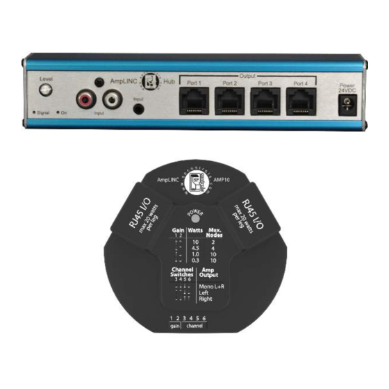
- Page 6 6 Technical Specifications 2 System Overview SP Controls reserves the right to change features and specifications without notice. Maximum Output 20Hz - 20kHz 10W @ 8Ω The AmpLINC System by SP Controls consists of two key compo- Output per node nents: the AmpLINC Hub and the AmpLINC Puck.
- Page 7 5 Troubleshooting 2.2 Example System Setup Problem: Hub’s Power indicator does not turn on. Procedure: Check that the Hub is plugged into a live outlet. After you have ensured that it is not a power issue, check that you have a hot signal going into the inputs. If a signal is not detected, the hub will go into a sleep mode after 5 minutes to comply with Energy Star.
- Page 8 3.2.2. The AmpLINC Hub is a UL 2043 plenum-rated unit which can be safely installed in the plenum space. SP Controls recommends that the unit is secured in some fashion to prevent movement of the unit if one of the cables is pulled during installation of an am- plifier node.
- Page 9 (such as a network router or switch). They are not permanent damage. Ethernet capable and will damage other devices. NOTE: SP Controls will not be held responsible for dam- age to your AmpLINC System or connected equipment if the instructions in this manual are not followed.
- Page 10 3.2.1 Node Input Connections Gain Configuration The AmpLINC system utilizes Cat5 to send power as well as a ste- reo signal to each node on the line. For the initial connection be- The gain level on the Puck is adjustable from 0.3W to 10W using tween the AmpLINC Hub and an AmpLINC Puck, a Cat5 cable the DIP switches on the front of the unit.
Need help?
Do you have a question about the AmpLINC Puc and is the answer not in the manual?
Questions and answers