Table of Contents
Advertisement
Quick Links
Advertisement
Table of Contents

Summary of Contents for Photon Systems Instruments GMS 150
- Page 3 Manual Version: 2022/07 © PSI (Photon Systems Instruments), spol. s r.o. www.psi.cz This document and its parts can be copied or provided to a third party only with the express permission of PSI. The contents of this manual have been verified to correspond to the specifications of the device. However, deviations cannot be ruled out.
-
Page 4: Table Of Contents
7.1.3 Menu Tree ..............................16 Quick Guide ............................20 How to Set GMS 150 in Absolute Mode ..................... 20 How to Set GMS 150 in Percentage Mode ....................20 Warranty Terms and Conditions ......................21 Troubleshooting and Customer Support ....................21 List of Pictures ............................. -
Page 5: Safety Precautions
The device is primarily intended to mix CO and air. Mixing of other gasses must be always consulted with manufacturer. • Pressure regulator must be always used when connecting the GMS 150 with the gas tank. Never connect the gas tank directly to the GMS 150. •... -
Page 6: Technical Specification
ECHNICAL PECIFICATION GMS 150 GMS 150-MICRO Measuring principle Thermal mass flow measurement Thermal mass flow measurement ±0.5 % Rd plus ±0.1 % FS ±1.5 % Rd plus ±0.5 % FS Accuracy (Incl. Linearity) (±1 % FS for ranges 3 – 5 ml/min; ±2 % FS for ranges <... -
Page 7: General Description
The input and output gas connectors are Prestolok type allowing fast and secure connection to a variety of tubes. The GMS 150 can operate gas flows ranging from ml/min to tens of l/min. GMS 150 is typically used to control flow of air, carbon dioxide, and nitrogen. -
Page 8: Components Of The Gms 150 Device
EVICE Standard version of the GMS package consists: • Gas Mixing System GMS 150 (Fig. 1) • Cables and Connectors – Power cable, 5 m of Parker Prestolok tubing Ø 6 mm, 3 pieces of blinding plugs (Fig. 2) •... -
Page 9: Description Of The Gms 150 Device
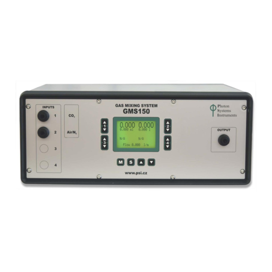
& Control Screen). 3) Four control keys for the device setting (more on device setting in Chapter 0 – Setting Screen). 4) Gas output. 5) Display. GMS 150 can produce precise mixtures of up to 4 different gasses, but standardly there are only two gas inputs. -
Page 10: Installation And Operation Protocol
An illustrative example of GMS 150 linked with PBR FMT 150: Recommended set-up includes one GMS 150 linked with one cultivation system (for example PBR FMT 150 unit) as is shown in Fig. 5. Such a configuration allows to use a full potential of GMS 150: •... - Page 11 Fig. 5 GMS 150 connection to Photobioreactor FMT 150 cultivation unit. Mixed gas of given composition is pumped from GMS (1) to the PBR FMT 150 (2) via air interruption valve (3), filter (4) and humidifier (5). Aeration gas is led through the cultivation vessel lid into the U-tube sparger. Medium overflow is collected using the medium outlet (6).
-
Page 12: Operation Instructions
PERATION NSTRUCTIONS The device is operated and controlled via two different screen-modes of the digital display: 1. Display & Control Screen – values for actual flow, target flow and output mixture flow of the gases are shown (Fig. 6 A). 2. -
Page 13: Display With Absolute Flow Units
7.1.1 D ISPLAY WITH BSOLUTE NITS Fig. 8 Display with absolute flow units. Values for current flow • The current flow values for gases used are shown on the top of the display, on left side is usually current gas flow for CO on the right side is usually current gas flow for Air/N (Fig. -
Page 14: Display With Percentage Gas Flow Units
7.1.2 D ISPLAY WITH ERCENTAGE NITS Fig. 9 Display with percentage gas flow units. Current percentage content • The current flow values for gases used are shown on the top of the display, on left side is usually current gas flow for CO on the right side is usually current gas flow for Air/N (Fig. - Page 15 Output mixture flow • The total flow of the gas mixture is determined by the instrument so that the percentage gas content is adjusted with a maximum accuracy. The user can optimize gas mixture flow using the Setting Screen → Press S key (below the digital display) to switch from the Display &...
-
Page 16: Menu Tree
Setting Menu Screen • The Setting Screen is operated by the M, S and UP/DOWN keys situated below the screen (see the picture below, Fig. 12). • Use the S key to switch from the Display & Control Screen to the Setting Screen and to confirm change in the menu tree or to save the selected value (parameter). - Page 17 Dev. Info (Fig. 14) This option specifies the device type, firmware version, firmware date, name and build number. Press S key (below the digital display) to switch from the Display & Control Screen to the Setting Screen. Use UP/DOWN keys for moving in menu and press S key on option Device Info.
- Page 18 Valve Info (Fig. 15) This option displays information about the installed valves (number of inputs, condition, valve type, maximum flow). Fig. 15 Menu Tree – Valve Info. Mode This option is used to switch between absolute and percentage flow mode. Press S key (below the digital display) to switch from the Display &...
- Page 19 Fig. 16 Main menu. Page | 19...
-
Page 20: Quick Guide
UICK UIDE 8.1 H GMS 150 OW TO BSOLUTE • Press S key to switch from the Display & Control Screen to the Setting Screen. • Use UP/DOWN keys for moving in menu and press S key on option Mode. Use UP/DOWN key to set the absolute mode and press S key to confirm. -
Page 21: Warranty Terms And Conditions
ONDITIONS • This Limited Warranty applies only to the Gas Mixing System GMS 150. It is valid one year from the date of shipment. • If at any time within this warranty period the instrument does not function as warranted, return it and the manufacturer will repair or replace it at no charge. -
Page 22: List Of Pictures
Fig. 3 GMS front panel....................................9 Fig. 4 GMS rear panel....................................9 Fig. 5 GMS 150 connection to Photobioreactor FMT 150 cultivation unit....................11 Fig. 6 A) Display & Control Screen. B) Setting Screen..........................12 Fig. 7 UP/DOWN keys....................................12 Fig.
Need help?
Do you have a question about the GMS 150 and is the answer not in the manual?
Questions and answers