
Subscribe to Our Youtube Channel
Summary of Contents for Ceyear 387 Series
- Page 1 387XX Series Solid-State Power Amplifier User Manual ООО «4ТЕСТ» Телефон: +7 (499) 685-4444 info@4test.ru www.4test.ru...
-
Page 2: Table Of Contents
Contents Contents Chapter 1 Overview ............................1 Chapter 2 Unpacking ............................2 Chapter 3 Operation Guide ..........................3 Section 1 Front Panel Features ..........................3 Section 2 Rear Panel Features ..........................4 Chapter 4 Working Principles .......................... 5 Chapter 5 Technical Indicators and Indicator Tests .................. -
Page 3: Chapter 1 Overview
Chapter 1 Overview Chapter 1 Overview 387XX series solid-state power amplifiers are a new series of microwave and millimeter-wave amplifiers. This series is easy to carry and operate. Its most prominent characteristics are wide band, high gain and high power. This series consists of multiple amplifiers operating in different frequency bands. Please refer to Chapter 5 Technical Indicators for their models and corresponding operating frequencies. -
Page 4: Chapter 2 Unpacking
Chapter 2 Unpacking Chapter 2 Unpacking Model confirmation When you open the package, you will see the following items: Solid-state power amplifier 3-core power cable User Manual Packing list Please check carefully for any incorrect or missing items against the order contract and the packing list. If there is any problem, please contact our operation center according to the contact information in the preface, and we will solve it as soon as possible. -
Page 5: Chapter 3 Operation Guide
Chapter 3 Operation Guide Chapter 3 Operation Guide The 387XX series solid-state power amplifiers cover a frequency range of 1GHz - 60 GHz and a unit output power range of 1 W – 100 W. Adopting the most advanced broadband space power synthesis technology in the world at present, they have completely independent intellectual property rights and adopt the external structure as standard bench top instruments. -
Page 6: Section 2 Rear Panel Features
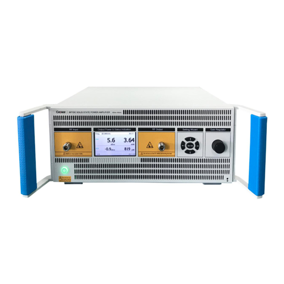
Chapter 3 Operation Guide display of the output powers of the amplifiers. RF Input connector The RF input connector is used for inputting the RF input signals of the solid-state power amplifier. RF Output connector The RF output connector is used for outputting the RF output signals of the solid-state power amplifier. Gain (Power) Regulator 387XX series solid-state power amplifiers are equipped with the Gain (Power) regulators on the front panels, allowing for adjustment of the gains or output powers of the amplifiers as required. -
Page 7: Chapter 4 Working Principles
Chapter 4 Working Principles Chapter 4 Working Principles The solid-state power amplifier amplifies the input signal power to generate the output signal power, the power supply module provides the DC voltage required by the 387XX series solid-state power amplifier, the bias plate provides the bias voltage for the solid-state power amplifier, and the power measurement unit converts the coupled detection output voltage signal from the solid-state power amplifier into RF output power displayed in dBms and Watts on the LCD screen of the front panel. -
Page 8: Chapter 5 Technical Indicators And Indicator Tests
Chapter 5 Technical Indicators and Indicator Tests Chapter 5 Technical Indicators and Indicator Tests Section 1 Main Indicators and Performance Characteristics Technical indicators of 387XX series solid-state power amplifiers Different models and main technical indicators are shown in the table below: Saturated output Working frequency Gain... - Page 9 Chapter 5 Technical Indicators and Indicator Tests Typical curve for constant-temperature output power of 387XX series solid-state power amplifiers (for reference only): 3871LA Output power VS Frequency 3871FF Output power VS Frequency 3871FB Output power VS Frequency 3871FA Output power VS Frequency 3871EA Output power VS Frequency 3871DA...
-
Page 10: Section 2 Indicator Tests
Chapter 5 Technical Indicators and Indicator Tests General Characteristics 2.1 Environmental Requirements Working temperature range: 0℃~+40℃ Storage temperature range: -40℃~+70℃ 2.2 Power Conditions AC 220V±10%, 50Hz±5%. Section 2 Indicator Tests Let’s take the indicator testing of 3871FB solid-state power amplifier as an example, which can be used as a reference for other models of solid-state power amplifiers. - Page 11 Chapter 5 Technical Indicators and Indicator Tests Gain testing steps: Turn on the power of the amplifier and 3672 for preheating for 30 minutes. Set 3672 to [Test], [S21], [Format], [Log Amplitude], power of -40dBm, frequency of 32 GHz to 40 GHz, frequency sweep time of 1s, and number of measurement points of 101.
- Page 12 Chapter 5 Technical Indicators and Indicator Tests the signal source connected to the input port of the amplifier to 0dBm or any other value that can make the amplifier in the working state of saturated output, record the reading on the power meter at each test frequency point, and calculate the sum of the max.
- Page 13 Chapter 5 Technical Indicators and Indicator Tests test method of 1dB compression point for the output power of the amplifier, and record the difference between the peak value of fundamental wave and the non-harmonic wave of the spectrum analyzer, which should meet the indicator requirements at most operating frequency points.
-
Page 14: Chapter 6 Maintenance And Repair
Chapter 6 Maintenance and Repair Chapter 6 Maintenance and Repair Section 1 Regular Maintenance Testing and Calibration 387XX series solid-state power amplifiers should be tested and calibrated regularly on a yearly basis. The testing period should be reduced accordingly if the instruments are working in severe environments. Surface Cleaning Wipe the front panel and the housing with a cloth dipped in a neutral detergent, and then wipe it with a dry cloth.
Need help?
Do you have a question about the 387 Series and is the answer not in the manual?
Questions and answers