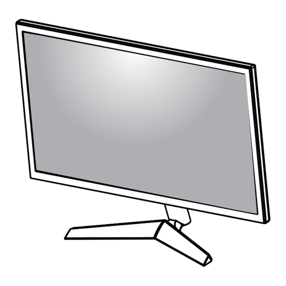
LG 24GL600F Service Manual
Chassis : lm91a
Hide thumbs
Also See for 24GL600F:
- Owner's manual (34 pages) ,
- Manual (8 pages) ,
- Instructions manual (8 pages)

Related Manuals for LG 24GL600F


Summary of Contents for LG 24GL600F
- Page 1 Internal Use Only LED MONITOR SERVICE MANUAL SERVICE MANUAL CHASSIS : LM91A MODEL :24GL600F/24GN50W CAUTION BEFORE SERVICING THE CHASSIS, READ THE SAFETY PRECAUTIONS IN THIS MANUAL. P/NO :MFL69406855(2003-REV01)
-
Page 2: Table Of Contents
SPECIFICATION ..................4 Firmware Upgrade Method ............... 8 TROUBLE SHOOTING GUIDE .............. 11 BLOCK DIAGRAM ................. 15 EXPLODED VIEW .................. 16 DISASSEMBLY ..................17 - 2 - Copyright © LG Electronics. Inc. All rights reserved. Only for training and service purposes... -
Page 3: Safety Precautions
When the exposed metal has no return path to the chassis the reading must be infinite. An other abnormality exists that must be corrected before the receiver is returned to the customer. - 3 - Copyright © LG Electronics. Inc. All rights reserved. Only for training and service purposes... -
Page 4: Specification
SET accessory Weight : 0.091kg± 10% 100 Ω± 10% Cable HDMI P/N : EAD63954401 CABLE : 100Ω±10Ω CONNECTOR : 100Ω±15Ω -4 - Copyright © LG Electronics. Inc. All rights reserved. LGE Internal Use Only Only for training and service purposes... - Page 5 Factory calibration report 0.002kg Checked SET accessory / Refer to BOM P/No Specification Applying module list MT236FHM-N10 EAJ64809601/2 Checked (BOE) Copyright © LG Electronics. Inc. All rights reserved. -5 - LGE Internal Use Only Only for training and service purposes...
- Page 6 235.5 1920 x 1080 V(Lines) 99.93 1133 1080 H(Pixels) 158.11 2056 1920 325.08 1920 x 1080 V(Lines) 144.00 1098 1080 Copyright © LG Electronics. Inc. All rights reserved. -6 - LGE Internal Use Only Only for training and service purposes...
- Page 7 (Preset Mode) (KHz) (Hz) 480P 31.5 576P 31.25 720P 37.5 720P 1080P 56.25 1080P 67.5 1080P 112.5 1080P -7 - Copyright © LG Electronics. Inc. All rights reserved. LGE Internal Use Only Only for training and service purposes...
-
Page 8: Firmware Upgrade Method
To PC USB port port 2. Unzip the driver file below and then install it depending on Windows OS. MstarDebugTool_Driver_Win7.zip 3. Reboot the PC after completed the installation. Copyright © 2012 LG Electronics Inc. All rights reserved. Only for training and service purposes... - Page 9 How to download monitor Firmware ▶ F/W Update Instruction 1. Connect HDMI cable and select “Connect” button. 2. Select “Read” button(1st) and find bin file(2nd) and then check the checksum value(3th).
- Page 10 How to download monitor Firmware 3. Select “Auto” button(1st) and confirm the checkbox settings(2nd) and then select “Run” button(3th). *Please make sure that “File Area” option is selected. 4. After ISP is completed, do factory reset in the OSD main menu.
-
Page 11: Trouble Shooting Guide
8.a. Trouble shooting Guide : No Power Copyright © 2012 LG Electronics Inc. All rights reserved. Only for training and service purposes... - Page 12 8.b. Trouble shooting Guide : No Screen on Copyright © 2012 LG Electronics Inc. All rights reserved. Only for training and service purposes...
- Page 13 8.c. Trouble shooting Guide : No video – HDMI Copyright © 2012 LG Electronics Inc. All rights reserved. Only for training and service purposes...
- Page 14 8.c. Trouble shooting Guide: No video – DP Copyright © 2012 LG Electronics Inc. All rights reserved. Only for training and service purposes...
-
Page 15: Block Diagram
BLOCK DIAGRAM 1. PCB P/N : EAX68305001 (1.1) 2. PCB Size : 160 x 141.5 mm 3. PCB Layer : 4 Layer (1.6T) LVDS LVDS ( 51pin) ( 41pin) DP Input (JK102) EEPROM Flash Memory (IC202) (IC201) HDMI 1 (JK100) MST9U17Q1 HDMI 2 (JK101) -
Page 16: Exploded View
EXPLODED VIEW IMPORTANT SAFETY NOTICE Many electrical and mechanical parts in this chassis have special safety-related characteristics. These parts are identified by in the Schematic Diagram and EXPLODED VIEW. It is essential that these special safety parts should be replaced with the same components as recommended in this manual to prevent Shock, Fire, or other Hazards. -
Page 17: Disassembly
SVC Disassembly guidance 1. Put on the Pad 2. Use a screw –driver to disassembly the Stand-base screw(1ea) 3. Disassembly the Stand-base. 4. Disassembly the Screw-cover... - Page 18 8. Use a jig to disassembly the Back cover. 5. Disassembly the Stand-body screw (2ea) 6. Disassembly the Stand-Body shaking left and right. 9. Disassembly the Control PCB assy toward Arrow direction. 7. Disassembly the Jack screw (1ea)
- Page 19 14. Pull out the Module from Cabinet 11. Disassembly the Metal Hinge assy and DMS assy 12. Disassembly the PCB Screw (2ea) 13. Pull out the PCB from Mainframe(Press).
Need help?
Do you have a question about the 24GL600F and is the answer not in the manual?
Questions and answers