Advertisement
Quick Links
Q U I C K I N S T A L L G U I D E
Installing the Enphase Communications Kit 2
The Communications Kit 2 (SKU: COMMS-KIT-02) enables wired communication between IQ Gateway, IQ Battery 5P, and IQ System Controller 3/3G.
✓
The Communications Kit 2 must be installed when an IQ Battery 5P is being used with the IQ Gateway (standalone or integrated into an IQ
NOTE:
Combiner 4/4C/3/3C/3-ES/3C-ES) instead of an IQ Combiner 5/5C. The IQ Combiner 5/5C integrates the functionality of the Communications
Kit 2 and therefore does not require a standalone Communications Kit 2.
Read and follow all warnings and instructions in this guide. If you need help understanding any of the concepts, terminology, or hazards outlined in these
instructions, refer installation to a qualified electrician or installer. These instructions are not meant to be a complete explanation of a renewable energy
system. All installations must comply with local codes and standards.
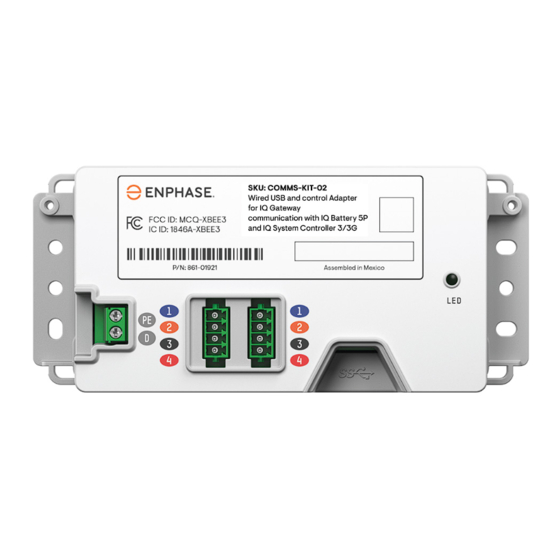
Figure 1: Communications Kit 2 enclosure view
CONTENTS
The Communications Kit 2 enables the IQ Gateway to communicate with
the IQ Battery 5P and/or IQ System Controller 3/3G over the control
cable.
This kit contains:
•
NEMA 3R enclosure with two DIN-rails mounted.
•
Control adapter mounted on lower din rail.
•
IQ Battery CT (leads must be wired to IQ Combiner terminals, as
shown in Section 6 of the
stalled on the aggregate IQ Battery Line 2 wire landing in IQ System
Controller 3 for multi-mode systems, IQ Combiner, or panel for
grid-interactive systems).
•
One - USB Type-C to Type-A cable (40 cm/15 ¾ inch).
•
Accessories bag including:
–
Zip ties for wire management.
–
Jumper (for shorting the IQ Gateway L2 and L3 power termi-
nals. Provided with this product for ease of system installation).
✓
For installation on sites containing the Envoy S Metered,
NOTE:
a 3-pin Wago that can fit into ports supporting 14 AWG wires
must be purchased separately.
–
Two control headers pre-installed on the kit (one extra header
provided as a spare).
The USB cable connects the Communications Kit 2 adapter to the IQ
Gateway. This also powers the Communications Kit adapter by drawing
power from the IQ Gateway.
The Control cable is wired to the detachable headers attached to the
adapter.
© 2023 Enphase Energy. All rights reserved. Enphase, the e and CC logos, IQ, and certain other marks listed at
https:/ /enphase.com/trademark-usage-guidelines
tries. Data subject to change. Rev 02/2023-07-10
(Model: COMMS-KIT-02)
IQ Combiner 4/4C
QIG. CT must be in-
are trademarks of Enphase Energy, Inc. in the US and other coun-
Figure 2: Control adapter
INSTALLATION
The installation section is divided into three sections.
1 )
Preparation
2 )
Product installation and wiring
3 )
Control (CTRL) wiring between system components and Commu-
nications Kit 2
DANGER! Risk of electric shock. All sources to equipment
being serviced must be disconnected external to the device.
In particular, the storage system may energize conductors, so
storage circuits must ALWAYS be isolated via a circuit breaker
or disconnected before working on any portion of the system.
Preparation
1
•
The Communications Kit 2 enclosure should have access to a ground
bar.
•
Identify your system design from the system wiring section below. The
control wiring installation varies based on the system design. You can
identify the Communications Kit wiring based on how the system will
be wired.
•
Identify a vertical location where the enclosure can be mounted. Keep
in mind the dimensions of the enclosure when finding a location.
•
It is recommended to power down the system before you begin to en-
sure safety while operating near electrical equipment and power wires.
•
Ensure you have the following tools for the installation:
–
Drill bit (required to drill holes for the conduit).
–
Screwdrivers, pliers, and a torque wrench.
Advertisement

Subscribe to Our Youtube Channel
Summary of Contents for enphase Communications Kit 2
- Page 1 The Communications Kit 2 (SKU: COMMS-KIT-02) enables wired communication between IQ Gateway, IQ Battery 5P, and IQ System Controller 3/3G. ✓ The Communications Kit 2 must be installed when an IQ Battery 5P is being used with the IQ Gateway (standalone or integrated into an IQ NOTE: Combiner 4/4C/3/3C/3-ES/3C-ES) instead of an IQ Combiner 5/5C.
- Page 2 Communications Kit 2. If the Communications Kit 2 is a terminating node, then only one wire leads into the Communications Kit enclosure. The other will contain ✓...
- Page 3 Figure 7: Control wiring for terminating node G ) Grounding the Communications Kit 2 From the potential earth port on the Communications Kit 2, there is a pre-wired cable connected to the pre-installed ground terminal. Draw an appropriately sized wire from a panel/IQ Combiner/IQ System Controller to ground the ground terminal inside the Communication Kit 2.
- Page 4 If the IQ Gateway has not been installed inside the Communications Kit 2 enclosure or this is being used to upgrade an IQ Combiner 3 or 4 system to work with IQ Battery 5P and IQ System Controller 3/3G, then draw the USB cable outside the Communications Kit 2 enclosure and into the enclosure housing the IQ Gateway.
- Page 5 Sequence 2: Enphase Communications Kit 2 - IQ Battery(s) 5P - IQ System Controller 3/3G Sequence 3: IQ System Controller 3/3G - Enphase Communications Kit 2 - IQ Battery(s) 5P Sequence 4: Enphase Communications Kit 2 - IQ System Controller 3 - IQ Battery(s) 5P...
- Page 6 CON T RO L WIR IN G SEQ UEN CE TE R MIN ATIO N R ESISTO R LO CATIO N • Enphase Communications Kit 2 Enphase Communications Kit 2 - IQ System Controller 3G - IQ Battery(s) 5P • Last IQ Battery 5P in the daisy chain •...
-
Page 7: Safety Instructions
However, there is no guarantee that interfer- App Store or Android Play Store and open it to log in to your Enphase ence will not occur in a particular installation. If this equipment does cause harmful Installer App account.
Need help?
Do you have a question about the Communications Kit 2 and is the answer not in the manual?
Questions and answers