Table of Contents

Related Manuals for AQUATO K-PILOT 9.7


Summary of Contents for AQUATO K-PILOT 9.7
- Page 1 › Operation Manual AQUATO K-PILOT ® 9.7 Control PLEASE NOTE THE FOLLOWING: The installation manual and the operating diary must be kept di- rectly at the facility, so that both operators and qualified personnel can inspect it at any time.
- Page 2 AQUATO K-PILOT 9.7 Control Operation Manual ® ® Operation Manual AQUATO K-Pilot 9.7 Manufacturer AQUATO Umwelttechnologien GmbH ® Ernstmeierstr. 24 D-32052 Herford All rights reserved. Infringements will lead to compensation. Duplication and passing on to third parties is only allowed with the consent of the manufacturer.
-
Page 3: Table Of Contents
® Operation Manual AQUATO K-Pilot 9.7 I Table of contents I Table of contents ....................3 II List of abbreviations ..................8 Manufacturer’s declaration ................9 Important information ................. 10 General information ................10 Important information ................10 Safety instructions ..................13 General information on the safety information ........ - Page 4 4.2.5 Operation with additional pump ............ 18 Installation manual for the controller ............19 Safety instructions ................. 19 Installation of the K-Pilot 9.7 controller ..........20 Solenoid valve block ................21 Connections on the controller ..............22 Overview ....................22 Air connections..................
- Page 5 ® Operation Manual AQUATO K-Pilot 9.7 Operation as an SSB plant ................. 49 Commissioning of the controller ............49 Main display ..................52 Menu ..................... 53 9.3.1 Menu structure ................53 9.3.2 "Service" menu ................54 9.3.3 "Settings" menu ................66 9.3.4...
- Page 6 AQUATO K-PILOT 9.7 Control Operation Manual ® ® Operation Manual AQUATO K-Pilot 9.7 11.3.1 Menu structure ................112 11.3.2 "Service" menu ................113 11.3.3 "Settings" menu ................124 11.3.4 Other menus with displays or settings ........127 11.4 Presets ....................132 11.5...
- Page 7 ® Operation Manual AQUATO K-Pilot 9.7 Operation with UV lamp for hygienisation ..........168 Operation with precipitant dosing for phosphate precipitation ... 171 Error messages and troubleshooting ............. 174 Technical Data ................... 177 Operation log ..................... 178 Decommissioning and disposal .............. 179 19.1...
-
Page 8: List Of Abbreviations
Figure 13: Connection of 2nd float switch as flood detector ..............36 Figure 14: Connection of double float switch to K-Pilot 9.7 controller ..........37 Figure 15: K-Pilot 9.7 controller – connection of second and third compressor ........40 Figure 16: Clear water pump with external float switch ............... 41 Figure 17: K-Pilot 9.7 controller –... -
Page 9: Manufacturer's Declaration
K-Pilot 9.7 Manufacturer’s declaration Declaration of Conformity This certifies the conformity of the AQUATO K-Pilot 9.7 controller with the EC directives for CE marking. ® Device type: Electronic control devices for the automatic operation of a fully biological small wastewater treatment plant according to DIN... -
Page 10: Important Information
In addition, it automatically controls compressors and pumps. During operation, the units are current- and pressure-controlled in order to ensure operational safety. The K-Pilot 9.7 controller can be used to operate SSB, SBR, fixed bed and fluidised bed wastewater treatment plants. - Page 11 Modifications to the controller and unauthorised conversions are not permitted. The AQUATO ® K-Pilot 9.7 controller must be installed properly and in accordance with the installation instructions (see Chapter The Controller Operation Manual must be read carefully before installation and commissioning and the...
- Page 12 AQUATO K-PILOT 9.7 Control Operation Manual ® ® Operation Manual AQUATO K-Pilot 9.7 Installation work may only be carried out by qualified electricians. When working on the device, always pull out the power plug. Never operate a device that ► has a malfunction, ►...
-
Page 13: Safety Instructions
® Operation Manual AQUATO K-Pilot 9.7 Safety instructions General information on the safety information This manual contains basic instructions that must be observed during installation, commissioning and maintenance. The complete manual must be kept directly at the plant so that both the operator and qualified personnel can inspect it at any time. -
Page 14: Warning Symbols Used
AQUATO K-PILOT 9.7 Control Operation Manual ® ® Operation Manual AQUATO K-Pilot 9.7 Warning symbols used Below you will find an overview of the symbols used in this manual and their meanings: Warning of a danger point Warning of dangerous electrical voltage... -
Page 15: General Safety Instructions
Risk of electric shock in case of defective compressor or defective power cables. The fine-bubble aeration of AQUATO ® diffuser systems causes a water-air bubble mixture with a lower density than pure water. This reduces the buoyancy in the water. -
Page 16: Safety Instructions For Qualified Personnel
AQUATO K-PILOT 9.7 Control Operation Manual ® ® Operation Manual AQUATO K-Pilot 9.7 Safety instructions for qualified personnel Installation, maintenance and repairs may only be carried out by qualified personnel. Before carrying out the work, it must be ensured that the knowledge and skills of the personnel are adequate to the intended use, •... -
Page 17: Area Of Application Of The Controller
However, when operated with the K-Pilot 9.7 controller, one or more lifters can also be replaced by submersible motor pumps. The K-Pilot 9.7 controller allow allows the use of a float switch purely as a flood detector – with no effect on the cycle. -
Page 18: Further Operating Modes
Operation with double float With the K-Pilot 9.7 controller, it is possible to work with double float switches, i.e. to use one float switch for the lower switching point and another for the upper switching point, thereby increasing the buffer. In this case, however, it is not possible to use another float switch for an additional buffer. -
Page 19: Installation Manual For The Controller
® Operation Manual AQUATO K-Pilot 9.7 Installation manual for the controller Safety instructions Non-compliance with the following safety instructions may result in a limitation or complete loss of liability on the part of the manufacturer. The controller is intended for cabinet mounting. -
Page 20: Installation Of The K-Pilot 9.7 Controller
IP 54 cannot be guaranteed. Installation of the K-Pilot 9.7 controller The controller allows you to control different treatment processes with different equipment. The valves required for this are arranged outside the housing. -
Page 21: Solenoid Valve Block
® Operation Manual AQUATO K-Pilot 9.7 Attention: Direct solar radiation must be avoided with all installation variants. Place the controller in a shady and wind-protected location. Install a heating and/or cooling fan in climatically unfavourable locations. Install a cooling fan for larger compressors. -
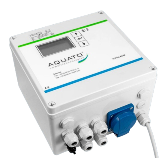
Page 22: Connections On The Controller
Connections on the controller Overview The display and the control buttons are on the front of the K-Pilot 9.7 controller. The bottom of the controller has a connection for the power cable, the socket for the compressor as well as cable bushings for the units to be connected and a connection for pressure measurement. - Page 23 At the top right is a serial interface RS232. Fuse Potential-free contact Terminals for electrical outputs and inputs Batteries Hose connection for pressure monitoring Cable bushings 230 V safety socket for compressor Figure 2: K-Pilot 9.7 controller opened Page 23...
-
Page 24: Air Connections
– in such a way that the various functions are assured. The K-Pilot 9.7 controller itself has only one air connection. This is used to measure the pressure in the controller. The controller has a pressure sensor for monitoring the pressure. A hose is led from this sensor to the controller housing. -
Page 25: Pressure Monitoring
® Operation Manual AQUATO K-Pilot 9.7 Pressure monitoring The controller has a pressure sensor for monitoring the pressure. A hose is led from this sensor to the controller housing. The hose connection is a 4 mm screw connection. A 4 mm hose connected to the air line between the compressor and the valves must be connected to this connection on the housing. -
Page 26: Electrical Connections
(see Assignment options for the electrical connectionsTable 3). Terminals for electrical outputs and inputs Row 1 (blue) Neutral conductor (N) Row 2 (grey) Phase (L) Row 3 (yellow-green) Earth (PE) Mains connection Socket for compressor Figure 5: Electrical connections of the K-Pilot 9.7 controller Page 26... -
Page 27: Arrangement And Function Of The Outputs And Inputs
Arrangement and function of the outputs and inputs The K-Pilot 9.7 controller has multiple electrical outputs and inputs for controlling the required units. The neutral conductor (N) of the unit to be connected is connected to the terminal strip in row 1 (in blue), the phase (L) in row 2 (in grey) and the earth (PE) in row 3 (in yellow-green). - Page 28 AQUATO K-PILOT 9.7 Control Operation Manual ® ® Operation Manual AQUATO K-Pilot 9.7 Function Fixed bed Moving bed 4 valves 3 valves 3 valves 2 valves Compressor Sludge recirculation Clear water discharge Charging Ventilation Table 1: Default assignment of the electrical connections with SBR, SSB, FB, MBBR...
-
Page 29: Mains Connection Of The Controller
After plugging in the plug, the controller starts with a self-test with a duration of approx. 3 seconds while displaying "booting system...". Then the start message "AQUATO" appears. The display Vx.xx.xx (e.g. V2.07.09) in the lower part of the message is the version number of the software. A few seconds later, the standard display appears. - Page 30 K-Pilot 9.7 Socket for compressor Figure 7: K-Pilot 9.7 controller with socket for compressor Attention: The compressor must not be connected to an external socket, as otherwise the aeration cycles will not be maintained. It must be connected to the designated socket on the side of the controller.
-
Page 31: Potential-Free Contact
® Operation Manual AQUATO K-Pilot 9.7 6.4.4 Potential-free contact The controller has a potential-free contact. It is located on the left-hand side of the circuit board. This contact can be used to connect a warning/flashing light in addition to the warning signals of the controller. - Page 32 AQUATO K-PILOT 9.7 Control Operation Manual ® ® Operation Manual AQUATO K-Pilot 9.7 If, in the event of a fault, the warning/flashing light should light up or flash to indicate the fault, select the connection via contacts 11 and 12 (see Figure 8).
-
Page 33: Solenoid Valves
6.4.5 Solenoid valves With the standard K-Pilot 9.7 controller, the solenoid valves are connected to the terminals T 2, T 3, T 4, and T 5, which are provided for this purpose. (For the required setting of the controller, please refer to the instructions for the process used). -
Page 34: Float Switch
A float switch can be used as an option. The float switch for the "Float" control type is connected to the K-Pilot 9.7 controller at terminals I 3 or I 2 provided for this purpose (see Figure 5). The float inputs are permanently occupied (see Table 4). - Page 35 K-Pilot 9.7 controller at terminal I 3 Figure 12: K-Pilot 9.7 controller – float switch connection 6.4.6.2 Float with control type "Time" as flood detector If the option "Time" control type is selected and the float switch is connected to terminal "I 3" provided for this purpose (this is the leftmost of the float connections, see Figure 12), the float works merely as a flood detector without intervening in the cycle sequence.
- Page 36 AQUATO K-PILOT 9.7 Control Operation Manual ® ® Operation Manual AQUATO K-Pilot 9.7 6.4.6.3 Second float as flood detector If the float switch for the "Float" control type is connected to the terminal "I 3" provided for this purpose and the "FLOAT" control type is selected during commissioning, a second float switch can also be connected to the terminal "I 2"...
- Page 37 Double Float With the K-Pilot 9.7 controller, it is possible to work with a double float switch. For this, the float switch (S1) for the "Double Float" control type is connected to terminal "I 3" provided for the purpose (see Figure 14).
- Page 38 AQUATO K-PILOT 9.7 Control Operation Manual ® ® Operation Manual AQUATO K-Pilot 9.7 6.4.6.5 Float BP With the float BP setting, the float switch intervenes in the SBR cycle in the following way: When the float switch floats up, charging is ended. The clear water discharge is not terminated when the float switch drops down.
-
Page 39: Further Assignments Of The Outputs
® Operation Manual AQUATO K-Pilot 9.7 6.4.7 Further assignments of the outputs 6.4.7.1 Compressor The compressor can be connected to outputs T1 to T7. Attention: The compressor must not be connected to an external socket, as otherwise the aeration cycles will not be maintained. - Page 40 K-Pilot 9.7 controller Connection cable to the K-Pilot 9.7 controller terminal T 5 Double safety socket for second and third compressor Figure 15: K-Pilot 9.7 controller – connection of second and third compressor Page 40...
- Page 41 ® Operation Manual AQUATO K-Pilot 9.7 6.4.7.4 Clear water pump A clear water pump is used to overcome greater delivery heads. This then replaces the clear water lifter. A pump and an external float switch are used. The float switch is attached to the pump holder of the clear water pump.
- Page 42 AQUATO K-PILOT 9.7 Control Operation Manual ® ® Operation Manual AQUATO K-Pilot 9.7 Standard connection for clear water pump in the K-Pilot 9.7 controller Figure 17: K-Pilot 9.7 controller – clear water pump connection Page 42...
- Page 43 ® Operation Manual AQUATO K-Pilot 9.7 6.4.7.5 Other connectible units If a surplus sludge pump or a charging pump is required, it can be connected in the same way as a clear water pump. In addition, a 2nd compressor, a UV system (always with float switch and clear water pump) or a dosing pump for phosphate precipitation (always with float switch) can be connected.
-
Page 44: Commissioning Of The Plant
AQUATO K-PILOT 9.7 Control Operation Manual ® ® Operation Manual AQUATO K-Pilot 9.7 Commissioning of the plant Prior to commissioning The relevant accident prevention regulations, guidelines, safety rules and leaflets of the responsible employers' liability insurance association (DGUV), as well as the regulations of the Association of German Electrical Engineers (VDE) must be observed when constructing and operating wastewater treatment plants. -
Page 45: Commissioning
Then the red LED lights up briefly and afterwards the green LED. At the same time, the start message "AQUATO" appears. The display Vx.xx.xx (e.g. V2.07.09) in the lower part of the message is the version number of the software. -
Page 46: Operation And Displays Of The Controller
AQUATO K-PILOT 9.7 Control Operation Manual ® ® Operation Manual AQUATO K-Pilot 9.7 Operation and displays of the controller Operation The controller has a graphic LCD display with 128 x 64 pixels. Indications are made in plain text and with two LEDs, one green, the other red. Operation is carried out via three buttons. -
Page 47: Faults
® Operation Manual AQUATO K-Pilot 9.7 You can also switch back from the submenus to the main menu level using the buttons. If the selection bar is moved in one direction until it disappears from the menu, the next main menu opens. -
Page 48: Power Failure Alarm
AQUATO K-PILOT 9.7 Control Operation Manual ® ® Operation Manual AQUATO K-Pilot 9.7 Power failure alarm The controller has a battery-powered power failure alarm. In the event of a power failure, an alarm tone sequence is generated approx. every 30 seconds in order to notify the operator that wastewater treatment has stopped. -
Page 49: Operation As An Ssb Plant
Then the red LED lights up briefly and afterwards the green LED. At the same time, the start message "AQUATO" appears on the display. The display Vx.xx.xx (e.g. V3.07.04) in the lower part of the message is the version number of the software. - Page 50 After ending manual mode, the controller continues to boot with the window "booting system..." and then "Fuse Check: values" with the message "Fuses o.k." before the start message "AQUATO" appears with the indication of the selected system type. Immediately afterwards, automatic mode is started automatically.
- Page 51 ® Operation Manual AQUATO K-Pilot 9.7 The commissioning engineer must ensure that the parameter settings in the controller have been made in such a way that they comply with the requirements (e.g. basic type and effluent class) of the approval and the water law license for the system on which the controller is to be used.
-
Page 52: Main Display
AQUATO K-PILOT 9.7 Control Operation Manual ® ® Operation Manual AQUATO K-Pilot 9.7 Main display In the standard display, the controller shows the switching status of the plant and the units, e.g.: 1st line: Date and time. 2nd line: Current SSB phase, e.g. "Sludge Discharge", "Pressure Monitoring", "Aeration", "Settling Phase", "Clear Water... -
Page 53: Menu
® Operation Manual AQUATO K-Pilot 9.7 Menu 9.3.1 Menu structure The "Denitrification" menu is only visible if denitrification is activated! See right for more Figure 19: Menu structure for SSB The exact appearance of the display depends on the status of the system and the set parameters. The different variants of the display are explained in more detail below. -
Page 54: Service" Menu
AQUATO K-PILOT 9.7 Control Operation Manual ® ® Operation Manual AQUATO K-Pilot 9.7 Use the buttons to move from menu to menu. If you move constantly in the same direction, you will eventually return to the standard display. To access the submenus in the menu displayed, the button must be pressed. - Page 55 Manual mode In addition to the "Compressor", "Clear Water" and "Sludge Recirculation" parameters, which are always available, the manual mode of the K-Pilot 9.7 controller allows further settings to be made. The exact display depends on the parameters set (during commissioning).
- Page 56 AQUATO K-PILOT 9.7 Control Operation Manual ® ® Operation Manual AQUATO K-Pilot 9.7 Three float switch symbols indicating the current float position are visible at the bottom left. If no float switch is connected, this corresponds to the symbol position down If a float switch is moved up and down, the indicator in the display changes accordingly.
- Page 57 ® Operation Manual AQUATO K-Pilot 9.7 9.3.2.3 Factory settings Under "FACTORY SETTINGS", the current error limit can be changed. The resetting of the controller, which is also possible in the factory settings, is not permitted throughout operation. Access to the factory settings is possible with password 2 only.
- Page 58 AQUATO K-PILOT 9.7 Control Operation Manual ® ® Operation Manual AQUATO K-Pilot 9.7 The "DELETE COUNTER" window opens. If "NO" is selected, the menus with the individual units are skipped and the "DELETE LOG" window opens immediately. → Answer: "NO".
- Page 59 ® Operation Manual AQUATO K-Pilot 9.7 9.3.2.4 Selecting a plant type In this menu, you can set/change the plant type and size, as well as other parameters required for operation. Select the menu item "SELECT PLANT TYPES". Then enter password 1 – or, for further settings, password 2 – digit by digit and confirm with the button to enter the menu.
- Page 60 All parameters for the treatment cycle are automatically preset through this selection, but can be readjusted if necessary. For plant sizes from 21 to 50 PE, please select "AQUATO>20 STABI SSB". The cycle presets for plant sizes from 21 to 50 PE are the same;...
- Page 61 ® Operation Manual AQUATO K-Pilot 9.7 If "DENITRIFICATION" is desired/required, it can be activated in the next window. The desired option can be selected in the second line. Use the buttons to select "YES" or "NO". The selected state is accepted with the middle button.
- Page 62 AQUATO K-PILOT 9.7 Control Operation Manual ® ® Operation Manual AQUATO K-Pilot 9.7 The additional functions follow directly and start with the next window with the query as to whether you require hygienisation: If you require hygienisation, use the buttons to select the option "YES"...
- Page 63 ® Operation Manual AQUATO K-Pilot 9.7 If a compressed air lifter is used for the surplus sludge discharge, please use the buttons to select "AIRLIFT PUMP" in the "SLUDGE DISCHARGE" window. If the surplus sludge discharge is equipped with a submersible motor pump instead of the compressed air lifter, please select "MOTOR PUMP"...
- Page 64 AQUATO K-PILOT 9.7 Control Operation Manual ® ® Operation Manual AQUATO K-Pilot 9.7 If you are operating a plant with 2 (or 3) compressors, please use buttons to select "YES" in the window with the query "2nd COMPRESSOR". If you do not require this option, please answer the query with "NO".
- Page 65 ® Operation Manual AQUATO K-Pilot 9.7 If you have selected a three-phase compressor, you will be asked in the "CURRENT MONITORING" window whether the three- phase compressor should be monitored for current errors. If you do not require this monitoring, you can switch it off with "NO".
-
Page 66: Settings" Menu
AQUATO K-PILOT 9.7 Control Operation Manual ® ® Operation Manual AQUATO K-Pilot 9.7 9.3.3 "Settings" menu The operator settings can be configured in the "SETTINGS" menu. Press the middle button to enter the menu to select the desired item. 9.3.3.1... - Page 67 ® Operation Manual AQUATO K-Pilot 9.7 9.3.3.3 Alarm buzzer ("Alarm pause") By default, the acoustic alarm is switched off from 17:00 to 6:00. During this time, errors are only displayed optically. This setting can be changed in the menu item "ALARM PAUSE".
- Page 68 AQUATO K-PILOT 9.7 Control Operation Manual ® ® Operation Manual AQUATO K-Pilot 9.7 9.3.3.5 Delete alarm If a fault (alarm) has occurred, the alarm message can be reset by pressing the button after selecting the "CLEAR ALARM" line. A window with the message "OK" opens for approx. 1 second and then the display in the menu changes to "NO ERRORS".
-
Page 69: Other Menus With Displays Or Settings
® Operation Manual AQUATO K-Pilot 9.7 9.3.4 Other menus with displays or settings In the following menus, all current parameters of the plant can be displayed and, in some cases, individually set. An adjustment may only be performed by a specialist, as the purification performance of the system may be reduced under certain circumstances and the national technical approval may become void. - Page 70 AQUATO K-PILOT 9.7 Control Operation Manual ® ® Operation Manual AQUATO K-Pilot 9.7 9.3.4.3 Ventilation The "AERATION" menu displays the selected aeration intervals in normal mode, i.e. for how many minutes aeration is alternately switched "ON" / "OFF" (clocking). In addition, it displays the total aeration duration ("DURATION:").
- Page 71 ® Operation Manual AQUATO K-Pilot 9.7 9.3.4.4 Denitrification Note: This menu is only visible if denitrification is activated. The "DENITRIFICATION" menu displays the selected aeration intervals in normal mode, i.e. for how many minutes aeration is alternately switched ON / OFF (clocking).
- Page 72 AQUATO K-PILOT 9.7 Control Operation Manual ® ® Operation Manual AQUATO K-Pilot 9.7 9.3.4.5 Parameters 1 Different parameters are displayed in the "PARAMETERS 1" menu depending on the setting. The parameters "SLUDGE DISCHARGE", "SETTLING PHASE" and "CLEAR WATER DISCHARGE" are always available.
- Page 73 ® Operation Manual AQUATO K-Pilot 9.7 9.3.4.6 Parameters 2 Different parameters are displayed in the "PARAMETERS 2" menu depending on the setting. The parameters "CURRENT MONITORING" and "MIN. CURRENT" are always available. If the controller switches on a unit (e.g. the compressor or a pump), it is not ensured with certainty that it will run.
- Page 74 AQUATO K-PILOT 9.7 Control Operation Manual ® ® Operation Manual AQUATO K-Pilot 9.7 9.3.4.7 Parameters 3 Various parameters may be displayed and adjusted in the "PARAMETERS 3" menu depending on the presetting. The exact appearance of the menu depends on the respective presets.
- Page 75 ® Operation Manual AQUATO K-Pilot 9.7 9.3.4.8 Pressure displays This menu displays the respective pressure during the last cycle. The clear water and surplus sludge counterpressures are each stored for each individual process. Only the pressure measurement of the respective last phase is displayed.
- Page 76 AQUATO K-PILOT 9.7 Control Operation Manual ® ® Operation Manual AQUATO K-Pilot 9.7 In this example, the compressor is controlled via output T1, the Outputs clear water discharge via output T3 and the sludge discharge via output T2. In addition, a three-phase compressor is controlled via output T5.
- Page 77 ® Operation Manual AQUATO K-Pilot 9.7 Here, output T4 was selected. Outputs Exit the menu with the buttons. You can find further setup options for the special function in the "PARAMETERS 3" menu. A different output must be assigned to each selected function. No...
-
Page 78: Presets
AQUATO K-PILOT 9.7 Control Operation Manual ® ® Operation Manual AQUATO K-Pilot 9.7 Presets Number of inhabitants: Aeration 1st C.: Control type: Time Denitrification: Switching times – Basic settings Aeration Aeration Denitrification Denitrification Normal mode Economy mode Normal mode Economy mode 15.0... -
Page 79: Operation As An Sbr Plant
Then the red LED lights up briefly and afterwards the green LED. At the same time, the start message "AQUATO" appears on the display. The display Vx.xx.xx (e.g. V3.07.04) in the lower part of the message is the version number of the software. - Page 80 AQUATO K-PILOT 9.7 Control Operation Manual ® ® Operation Manual AQUATO K-Pilot 9.7 Date and time Basic plant type – here select: "SBR" Valve for aeration YES / NO Plant size, e.g. "4 PE" Control type: "TIME", "FLOAT" or "DOUBLE FLOAT"...
- Page 81 ® Operation Manual AQUATO K-Pilot 9.7 The commissioning engineer must ensure that the parameter settings in the controller have been made in such a way that they comply with the requirements (e.g. basic type and effluent class) of the approval and the water law license for the system on which the controller is to be used.
-
Page 82: Main Display
AQUATO K-PILOT 9.7 Control Operation Manual ® ® Operation Manual AQUATO K-Pilot 9.7 Main display 10.2 In the standard display, the controller shows the switching status of the plant and the units, e.g.: 1st line: Date and time 2nd line: Current SBR phase, including "Charging,"... -
Page 83: Menu
® Operation Manual AQUATO K-Pilot 9.7 Menu 10.3 10.3.1 Menu structure In the "Aeration" and "Denitrification" menus, economy mode is only visible if a float switch is installed and set. See right for more Figure 20: Menu structure for SBR The exact display depends on the status of the system and the set parameters. -
Page 84: Service" Menu
AQUATO K-PILOT 9.7 Control Operation Manual ® ® Operation Manual AQUATO K-Pilot 9.7 Use the buttons to move from menu to menu. If you move constantly in the same direction, you will eventually return to the standard display. To access the submenus in the menu displayed, the middle button must be pressed. - Page 85 In addition to the "Compressor", "Charging", "Clear Water" and "Sludge Recirculation" parameters, which are always available, the manual mode of the K-Pilot 9.7 controller allows further settings to be made. The exact display depends on the parameters set (during commissioning).
- Page 86 AQUATO K-PILOT 9.7 Control Operation Manual ® ® Operation Manual AQUATO K-Pilot 9.7 Three float switch symbols indicating the current float position are visible at the bottom left. If no float switch is connected, this corresponds to the symbol position down If a float switch is moved up and down, the indicator in the display changes accordingly.
- Page 87 ® Operation Manual AQUATO K-Pilot 9.7 10.3.2.3 Factory settings Under "FACTORY SETTINGS", the current error limit can be changed. The resetting of the controller, which is also possible in the factory settings, is not permitted throughout operation. Access to the factory settings is possible with password 2 only.
- Page 88 AQUATO K-PILOT 9.7 Control Operation Manual ® ® Operation Manual AQUATO K-Pilot 9.7 The "DELETE COUNTER" window opens. If "NO" is selected, the menus with the individual units are skipped and the "DELETE LOG" window opens immediately. → Answer: "NO".
- Page 89 ® Operation Manual AQUATO K-Pilot 9.7 10.3.2.4 Selecting a plant type In this menu, you can set/change the plant type and size, as well as other parameters required for operation. Select the menu item "SELECT PLANT TYPES". Then enter password 1 – or, for further settings, password 2 – digit by digit and confirm with the button to enter the menu.
- Page 90 All parameters for the treatment cycle are automatically preset through this selection, but can be readjusted if necessary. For plant sizes from 21 to 50 PE, please select "AQUATO>20 KOM SBR". The cycle presets for plant sizes from 21 to 50 PE are the same;...
- Page 91 ® Operation Manual AQUATO K-Pilot 9.7 f "DENITRIFICATION" is desired/required, it can be activated in the next window. The desired option can be selected in the second line. Use the buttons to select "YES" or "NO". The selected state is accepted with the button.
- Page 92 AQUATO K-PILOT 9.7 Control Operation Manual ® ® Operation Manual AQUATO K-Pilot 9.7 The additional functions follow directly and start with the next window with the query as to whether you require hygienisation: If you require hygienisation, use the buttons to select the option "YES"...
- Page 93 ® Operation Manual AQUATO K-Pilot 9.7 If a compressed air lifter is used for charging, please use the buttons to select "AIRLIFT PUMP" in the "CHARGING" window. If the charging is equipped with a submersible motor pump instead of the compressed air lifter, please select "MOTOR PUMP" in the "CHARGING"...
- Page 94 AQUATO K-PILOT 9.7 Control Operation Manual ® ® Operation Manual AQUATO K-Pilot 9.7 If the additional pump is to be operated with an external float switch, please use the buttons to select the option "YES" in the "ADDITIONAL PUMP WITH FLOAT" window.
- Page 95 ® Operation Manual AQUATO K-Pilot 9.7 If you have selected a three-phase compressor, you will be asked in the "CURRENT MONITORING" window whether the three- phase compressor should be monitored for current errors. If you do not require this monitoring, you can switch it off with "NO".
-
Page 96: Settings" Menu
AQUATO K-PILOT 9.7 Control Operation Manual ® ® Operation Manual AQUATO K-Pilot 9.7 10.3.3 "Settings" menu The operator settings can be configured in the "SETTINGS" menu. Press the button to enter the menu to select the desired item. 10.3.3.1 Setting the date and time... - Page 97 ® Operation Manual AQUATO K-Pilot 9.7 10.3.3.3 Alarm buzzer ("Alarm pause") By default, the acoustic alarm is switched off from 17:00 to 6:00. During this time, errors are only displayed optically. This setting can be changed in the menu item "ALARM PAUSE".
- Page 98 AQUATO K-PILOT 9.7 Control Operation Manual ® ® Operation Manual AQUATO K-Pilot 9.7 10.3.3.5 Delete alarm If a fault (alarm) has occurred, the alarm message can be reset by pressing the button after selecting the "CLEAR ALARM" line. A window with the message "OK" opens for approx. 1 second and then the display in the menu changes to "NO ERRORS".
-
Page 99: Other Menus With Displays Or Settings
® Operation Manual AQUATO K-Pilot 9.7 10.3.4 Other menus with displays or settings In the following menus, all current parameters of the plant can be displayed and, in some cases, individually set. An adjustment may only be performed by a specialist, as the purification performance of the system may be reduced under certain circumstances and the national technical approval may become void. - Page 100 AQUATO K-PILOT 9.7 Control Operation Manual ® ® Operation Manual AQUATO K-Pilot 9.7 10.3.4.3 Ventilation The "AERATION" menu displays the selected aeration intervals in normal mode, i.e. for how many minutes aeration is alternately switched "ON" / "OFF" (clocking). In addition, it displays the total aeration duration ("DURATION:").
- Page 101 ® Operation Manual AQUATO K-Pilot 9.7 10.3.4.4 Denitrification Note: This menu is only visible if denitrification is activated. The "DENITRIFICATION" menu displays the selected aeration intervals in normal mode, i.e. for how many minutes aeration is alternately switched ON / OFF (clocking).
- Page 102 AQUATO K-PILOT 9.7 Control Operation Manual ® ® Operation Manual AQUATO K-Pilot 9.7 10.3.4.5 Parameters 1 Different parameters are displayed in the "PARAMETERS 1" menu depending on the setting. The parameters "CHARGING", "SLUDGE DISCHARGE", "SETTLING PHASE" and "CLEAR WATER DISCHARGE" are always available.
- Page 103 ® Operation Manual AQUATO K-Pilot 9.7 10.3.4.6 Parameters 2 Different parameters are displayed in the "PARAMETERS 2" menu depending on the setting. The parameters "CURRENT MONITORING" and "MIN. CURRENT" are always available. If the controller switches on a unit (e.g. the compressor or a pump), it is not ensured with certainty that it will run.
- Page 104 AQUATO K-PILOT 9.7 Control Operation Manual ® ® Operation Manual AQUATO K-Pilot 9.7 10.3.4.7 Parameters 3 Various parameters may be displayed and adjusted in the "PARAMETERS 3" menu depending on the presetting. The exact appearance of the menu depends on the respective presets.
- Page 105 ® Operation Manual AQUATO K-Pilot 9.7 10.3.4.8 Pressure displays This menu displays the respective pressure during the last cycle. The charging, clear water and surplus sludge counterpressures are each stored for each individual process. Only the pressure measurement of the respective last phase is displayed.
- Page 106 AQUATO K-PILOT 9.7 Control Operation Manual ® ® Operation Manual AQUATO K-Pilot 9.7 In this example, the compressor is controlled via output T1, Outputs charging via output T4, the clear water discharge via output T3 and the sludge discharge via output T2. In addition, a three-phase compressor is controlled via output T5.
- Page 107 ® Operation Manual AQUATO K-Pilot 9.7 The menu item is called up with the button. The settings are Outputs changed with the buttons. Select a free output – in the example: T5. To accept the settings, Outputs confirm by pressing the button.
-
Page 108: Presets
AQUATO K-PILOT 9.7 Control Operation Manual ® ® Operation Manual AQUATO K-Pilot 9.7 Presets 10.4 Number of inhabitants: Control type: Time Denitrification: Switching times – Basic settings 10.5 Aeration Aeration Denitrification Denitrification Normal mode Economy mode Normal mode Economy mode 1.0 15.0... -
Page 109: Operation As Fluidised Or Fixed Bed Plant
Then the red LED lights up briefly and afterwards the green LED. At the same time, the start message "AQUATO" appears on the display. The display Vx.xx.xx (e.g. V3.07.04) in the lower part of the message is the version number of the software. - Page 110 AQUATO K-PILOT 9.7 Control Operation Manual ® ® Operation Manual AQUATO K-Pilot 9.7 Language Date and time Basic plant type – here select: "FLUIDISED BED" or "FIXED BED" Plant size, e.g. "4 PE" Control type, here select: "TIME" with pressure monitoring YES / NO The following additional options can only be selected during commissioning if password 2 was entered (see Chapter 11.3.2.4):...
-
Page 111: Main Display
® Operation Manual AQUATO K-Pilot 9.7 Main display 11.2 In the standard display, the controller shows the switching status of the plant and the units, e.g.: 1st line: Date and time 2nd line: Current phase: "Aeration", "Sludge Discharge" and additional phases depending on the setting... -
Page 112: Menu
AQUATO K-PILOT 9.7 Control Operation Manual ® ® Operation Manual AQUATO K-Pilot 9.7 Menu 11.3 11.3.1 Menu structure See right for more Figure 21: Menu structure for fluidised/fixed bed plant The exact display depends on the status of the system and the set parameters. The different variants of the display are explained in more detail below. -
Page 113: Service" Menu
® Operation Manual AQUATO K-Pilot 9.7 Use the buttons to move from menu to menu. If you move constantly in the same direction, you will eventually return to the standard display. To access the submenus in the menu displayed, the middle button must be pressed. - Page 114 AQUATO K-PILOT 9.7 Control Operation Manual ® ® Operation Manual AQUATO K-Pilot 9.7 11.3.2.2 Manual mode In addition to the "Compressor" parameter, which is always available, the manual mode of the K-Pilot 9.7 controller allows further settings to be made. The exact display depends on the parameters set (during commissioning).
- Page 115 ® Operation Manual AQUATO K-Pilot 9.7 Three float switch symbols indicating the current float position are visible at the bottom left of the display. If no float switch is connected, this corresponds to the symbol position down If a float switch is moved up and down, the indicator in the display changes accordingly.
- Page 116 AQUATO K-PILOT 9.7 Control Operation Manual ® ® Operation Manual AQUATO K-Pilot 9.7 11.3.2.3 Factory settings Under "FACTORY SETTINGS", the current error limit can be changed. The resetting of the controller, which is also possible in the factory settings, is not permitted throughout operation. Access to the factory settings is possible with password 2 only.
- Page 117 ® Operation Manual AQUATO K-Pilot 9.7 The "DELETE COUNTER" window opens. If "NO" is selected, the menus with the individual units are skipped and the "DELETE LOG" window opens immediately. → Answer: "NO". If "YES" is selected, the controller moves on to the individual units each time the button is pressed.
- Page 118 AQUATO K-PILOT 9.7 Control Operation Manual ® ® Operation Manual AQUATO K-Pilot 9.7 11.3.2.4 Selecting a plant type In this menu, you can set/change the plant type and size, as well as other parameters required for operation. Select the menu item "SELECT PLANT TYPES".
- Page 119 ® Operation Manual AQUATO K-Pilot 9.7 The "CONTROL TYPE" window allows you to choose between a time-controlled cycle or a float-controlled cycle. The desired control type can be set in the second line. Press the buttons to select "TIME" or "FLOAT". The selected Control type is accepted with the button.
- Page 120 AQUATO K-PILOT 9.7 Control Operation Manual ® ® Operation Manual AQUATO K-Pilot 9.7 If you need a pump in addition to the standard wastewater treatment function, use the buttons to select the "ON" option in the second line of the next window, "MOTOR PUMP".
- Page 121 ® Operation Manual AQUATO K-Pilot 9.7 Then you are asked how the sludge discharge is to take place, with a submersible motor pump or with a compressed air lifter. If the sludge recirculation is to take place with a pump instead of a lifter, use the buttons to select the option "MOTOR PUMP"...
- Page 122 AQUATO K-PILOT 9.7 Control Operation Manual ® ® Operation Manual AQUATO K-Pilot 9.7 If you are operating a plant with 2 (or 3) compressors, please select "YES" in the window with the query "2nd COMPRESSOR". After completing the system type selection (or commissioning),...
- Page 123 ® Operation Manual AQUATO K-Pilot 9.7 If you have selected "YES" for the query "3~COMPRESSOR", you will be asked in the "CURRENT MONITORING" window whether the three-phase compressor should be monitored for current errors. If you do not require this monitoring, you can switch it off with "NO".
-
Page 124: Settings" Menu
AQUATO K-PILOT 9.7 Control Operation Manual ® ® Operation Manual AQUATO K-Pilot 9.7 11.3.3 "Settings" menu The operator settings can be configured in the "SETTINGS" menu. Press the button to enter the menu to select the desired item. 11.3.3.1 Setting the date and time... - Page 125 ® Operation Manual AQUATO K-Pilot 9.7 11.3.3.3 Alarm buzzer ("Alarm pause") By default, the acoustic alarm is switched off from 17:00 to 6:00. During this time, errors are only displayed optically. This setting can be changed in the menu item "ALARM PAUSE".
- Page 126 AQUATO K-PILOT 9.7 Control Operation Manual ® ® Operation Manual AQUATO K-Pilot 9.7 11.3.3.5 Delete alarm If a fault (alarm) has occurred, the alarm message can be reset by pressing the button after selecting the "CLEAR ALARM" line. A window with the message "OK" opens for approx. 1 second and then the display in the menu changes to "NO ERRORS".
-
Page 127: Other Menus With Displays Or Settings
® Operation Manual AQUATO K-Pilot 9.7 11.3.4 Other menus with displays or settings In the following menus, all current parameters of the plant can be displayed and, in some cases, individually set. An adjustment may only be performed by a specialist, as the purification performance of the system may be reduced under certain circumstances and the national technical approval may become void. - Page 128 AQUATO K-PILOT 9.7 Control Operation Manual ® ® Operation Manual AQUATO K-Pilot 9.7 11.3.4.3 Ventilation The "AERATION" menu displays the selected aeration intervals in day and in night mode, i.e. it displays for how many minutes aeration is alternately switched "ON" / "OFF" (clocking).
- Page 129 ® Operation Manual AQUATO K-Pilot 9.7 11.3.4.5 Parameters 2 Different parameters are displayed in the "PARAMETERS 2" menu depending on the setting. The parameters "CURRENT MONITORING" and "MIN. CURRENT" are always available. If the controller switches on a unit (e.g. the compressor or a pump), it is not ensured with certainty that it will run.
- Page 130 AQUATO K-PILOT 9.7 Control Operation Manual ® ® Operation Manual AQUATO K-Pilot 9.7 11.3.4.6 Parameters 3 Various parameters may be displayed and adjusted in the "PARAMETERS 3" menu depending on the presetting. The exact appearance of the menu depends on the respective presets.
- Page 131 ® Operation Manual AQUATO K-Pilot 9.7 11.3.4.7 Pressure displays This menu displays the respective pressure during the last cycle. The aeration and surplus sludge counterpressures are each stored for each individual process. Only the pressure measurement of the respective last phase is displayed.
-
Page 132: Presets
AQUATO K-PILOT 9.7 Control Operation Manual ® ® Operation Manual AQUATO K-Pilot 9.7 Presets 11.4 Number of inhabitants: Control type: Float Switching times – Basic settings 11.5 Aeration phase, Aeration phase, Aeration phase, Aeration phase, day mode night mode day mode... -
Page 133: Operation As A Trickling Filter Plant
® Operation Manual AQUATO K-Pilot 9.7 Operation as a trickling filter plant The small wastewater treatment plant must be operated by the owner or a competent person commissioned by the owner (operator). After commissioning, the plant is operated fully automatically. It is controlled by a PLC. The sequence and flow of the phases are programmed in the controller. - Page 134 AQUATO K-PILOT 9.7 Control Operation Manual ® ® Operation Manual AQUATO K-Pilot 9.7 Configuration A Units of the TYPE C trickling filter plant with 3 pumps 3-pump plant with 2 separate float switches for pump 2 Pump 1: Feed pump of the trickling filter pumps from pump chamber to TF and into PS...
- Page 135 ® Operation Manual AQUATO K-Pilot 9.7 Configuration B Units of the TYPE C trickling filter plant with 2 pumps 2-pump plant with 2 separate float switches for pump 2 Pump 1: active: NO Pump 2: Drain pump (corresponds to clear water pump) delivers from pump chamber to SS...
- Page 136 AQUATO K-PILOT 9.7 Control Operation Manual ® ® Operation Manual AQUATO K-Pilot 9.7 Configuration C Units of the TYPE N trickling filter plant with 2 pumps 2-pump plant with 1 separate float switch for pump 2 Pump 1: active: NO...
-
Page 137: Commissioning Of The Controller
. At the same time, the green LED lights up. After the indication "Fuse Check: values" with the message "Fuses o.k.", the start message "AQUATO" appears on the display. The display Vx.xx.xx (e.g. V5.01.04) in the lower part of the message is the version number of the software. - Page 138 AQUATO K-PILOT 9.7 Control Operation Manual ® ® Operation Manual AQUATO K-Pilot 9.7 The commissioning engineer must ensure that the parameter settings in the controller have been made in such a way that they comply with the requirements (e.g. basic type and effluent class) of the approval and the water law license for the system on which the controller is to be used.
-
Page 139: Main Display
® Operation Manual AQUATO K-Pilot 9.7 Main display 12.2 In the standard display, the controller shows the switching status of the plant and the units, e.g.: 1st line: Date and time 2nd line: Switching status of "PUMP 1:", "ON" or "OFF" and... -
Page 140: Menu
AQUATO K-PILOT 9.7 Control Operation Manual ® ® Operation Manual AQUATO K-Pilot 9.7 Menu 12.3 12.3.1 Menu structure See right for more Figure 23: Menu structure of Trickling Filter C and Trickling Filter N The exact display depends on the status of the system and the set parameters. The different variants of the display are explained in more detail below. -
Page 141: Service" Menu
® Operation Manual AQUATO K-Pilot 9.7 Use the buttons to move from menu to menu. If you move constantly in the same direction, you will eventually return to the standard display. To access the submenus in the menu displayed, the middle button must be pressed. - Page 142 AQUATO K-PILOT 9.7 Control Operation Manual ® ® Operation Manual AQUATO K-Pilot 9.7 12.3.2.2 Manual mode In manual mode of the K-Pilot 14.5 controller, the activated pumps can be operated for the basic types Trickling Filter C and Trickling Filter N, respectively. The exact display depends on the parameters set (during commissioning).
- Page 143 ® Operation Manual AQUATO K-Pilot 9.7 12.3.2.3 Factory settings Under "FACTORY SETTINGS", the current error limit can be changed. The resetting of the controller, which is also possible in the factory settings, is not permitted throughout operation. Access to the factory settings is possible with password 2 only.
- Page 144 AQUATO K-PILOT 9.7 Control Operation Manual ® ® Operation Manual AQUATO K-Pilot 9.7 In the next window, "HW error deactivated" the flooding error message can be deactivated. This is usually unnecessary. After confirming the selection, the next window opens automatically.
- Page 145 ® Operation Manual AQUATO K-Pilot 9.7 12.3.2.4 Selecting a plant type In this menu, you can set/change the plant type and size, as well as other parameters required for operation. Select the menu item "SELECT PLANT TYPES". Then enter password 1 – or password 2 – digit by digit and confirm with the button to enter the menu.
-
Page 146: Settings" Menu
AQUATO K-PILOT 9.7 Control Operation Manual ® ® Operation Manual AQUATO K-Pilot 9.7 12.3.3 "Settings" menu The operator settings can be configured in the "SETTINGS" menu. Press the button to enter the menu to select the desired item. 12.3.3.1 Setting the date and time... - Page 147 ® Operation Manual AQUATO K-Pilot 9.7 12.3.3.3 Alarm buzzer ("Alarm pause") By default, the acoustic alarm is switched off from 17:00 to 6:00. During this time, errors are only displayed optically. This setting can be changed in the menu item "ALARM PAUSE".
- Page 148 AQUATO K-PILOT 9.7 Control Operation Manual ® ® Operation Manual AQUATO K-Pilot 9.7 12.3.3.5 Delete alarm If a fault (alarm) has occurred, the alarm message can be reset by pressing the button after selecting the "CLEAR ALARM" line. A window with the message "OK" opens for approx. 1 second and then the display in the menu changes to "NO ERRORS".
-
Page 149: Other Menus With Displays Or Settings
® Operation Manual AQUATO K-Pilot 9.7 12.3.4 Other menus with displays or settings In the following menus, all current parameters of the plant can be displayed and, in some cases, individually set. An adjustment may only be performed by a specialist, as the purification performance of the system may be reduced under certain circumstances and the national technical approval may become void. - Page 150 AQUATO K-PILOT 9.7 Control Operation Manual ® ® Operation Manual AQUATO K-Pilot 9.7 12.3.4.2 Pump 1 to Pump 4 Different parameters are displayed in the "PUMP 1" to "PUMP 4" menus depending on the setting. The parameter "ACTIVE" is always included.
-
Page 151: Presets
® Operation Manual AQUATO K-Pilot 9.7 12.3.4.3 Parameters 2 The Parameters (1) menu is omitted for the trickling filter plant, as it has no function for this plant type. Different parameters are displayed in the "PARAMETERS (2)" menu depending on the setting. The parameters "CURRENT MEASUREMENT"... -
Page 152: Operation As A Constructed Wetland Plant
AQUATO K-PILOT 9.7 Control Operation Manual ® ® Operation Manual AQUATO K-Pilot 9.7 Operation as a constructed wetland plant The small wastewater treatment plant must be operated by the owner or a competent person commissioned by the owner (operator). After commissioning, the plant is operated fully automatically. It is controlled by a PLC. The sequence and flow of the phases are programmed in the controller. -
Page 153: Commissioning Of The Controller
. At the same time, the green LED lights up. After the indication "Fuse Check: values" with the message "Fuses o.k.", the start message "AQUATO" appears on the display. The display Vx.xx.xx (e.g. V5.01.04) in the lower part of the message is the version number of the software. - Page 154 AQUATO K-PILOT 9.7 Control Operation Manual ® ® Operation Manual AQUATO K-Pilot 9.7 The commissioning engineer must ensure that the parameter settings in the controller have been made in such a way that they comply with the requirements (e.g. basic type and effluent class) of the approval and the water law license for the system on which the controller is to be used.
-
Page 155: Main Display
® Operation Manual AQUATO K-Pilot 9.7 Main display 13.2 In the standard display, the controller shows the switching status of the plant and the units, e.g.: 1st line: Date and time 2nd line: Switching status of "PUMP 1:", "ON" or "OFF" and... -
Page 156: Menu
AQUATO K-PILOT 9.7 Control Operation Manual ® ® Operation Manual AQUATO K-Pilot 9.7 Menu 13.3 13.3.1 Menu structure See right for more Figure 24: Menu structure of Trickling Filter C and Trickling Filter N The exact display depends on the status of the system and the set parameters. The different variants of the display are explained in more detail below. -
Page 157: Service" Menu
® Operation Manual AQUATO K-Pilot 9.7 Use the buttons to move from menu to menu. If you move constantly in the same direction, you will eventually return to the standard display. To access the submenus in the menu displayed, the middle button must be pressed. - Page 158 AQUATO K-PILOT 9.7 Control Operation Manual ® ® Operation Manual AQUATO K-Pilot 9.7 13.3.2.2 Manual mode In manual mode of the K-Pilot 14.5 controller, the activated pumps can be operated for the basic types Trickling Filter C and Trickling Filter N, respectively. The exact display depends on the parameters set (during commissioning).
- Page 159 ® Operation Manual AQUATO K-Pilot 9.7 13.3.2.3 Factory settings Under "FACTORY SETTINGS", the current error limit can be changed. The resetting of the controller, which is also possible in the factory settings, is not permitted throughout operation. Access to the factory settings is possible with password 2 only.
- Page 160 AQUATO K-PILOT 9.7 Control Operation Manual ® ® Operation Manual AQUATO K-Pilot 9.7 In the next window, "HW error deactivated" the flooding error message can be deactivated. This is usually unnecessary. After confirming the selection, the next window opens automatically.
- Page 161 ® Operation Manual AQUATO K-Pilot 9.7 13.3.2.4 Selecting a plant type In this menu, you can set/change the plant type and size, as well as other parameters required for operation. Select the menu item "SELECT PLANT TYPES". Then enter password 1 – or password 2 – digit by digit and confirm with the button to enter the menu.
-
Page 162: Settings" Menu
AQUATO K-PILOT 9.7 Control Operation Manual ® ® Operation Manual AQUATO K-Pilot 9.7 13.3.3 "Settings" menu The operator settings can be configured in the "SETTINGS" menu. Press the button to enter the menu to select the desired item. 13.3.3.1 Setting the date and time... - Page 163 ® Operation Manual AQUATO K-Pilot 9.7 13.3.3.3 Alarm buzzer ("Alarm pause") By default, the acoustic alarm is switched off from 17:00 to 6:00. During this time, errors are only displayed optically. This setting can be changed in the menu item "ALARM PAUSE".
- Page 164 AQUATO K-PILOT 9.7 Control Operation Manual ® ® Operation Manual AQUATO K-Pilot 9.7 13.3.3.5 Delete alarm If a fault (alarm) has occurred, the alarm message can be reset by pressing the button after selecting the "CLEAR ALARM" line. A window with the message "OK" opens for approx. 1 second and then the display in the menu changes to "NO ERRORS".
-
Page 165: Other Menus With Displays Or Settings
® Operation Manual AQUATO K-Pilot 9.7 13.3.4 Other menus with displays or settings In the following menus, all current parameters of the plant can be displayed and, in some cases, individually set. An adjustment may only be performed by a specialist, as the purification performance of the system may be reduced under certain circumstances and the national technical approval may become void. - Page 166 AQUATO K-PILOT 9.7 Control Operation Manual ® ® Operation Manual AQUATO K-Pilot 9.7 13.3.4.2 Pump 1 to Pump 4 Different parameters are displayed in the "PUMP 1" to "PUMP 4" menus depending on the setting. The parameter "ACTIVE" is always included.
-
Page 167: Presets
® Operation Manual AQUATO K-Pilot 9.7 13.3.4.3 Parameters 2 The "Parameters 1" menu is omitted for the constructed wetland plant, as it has no function for this plant type. Different parameters are displayed in the "PARAMETERS (2)" menu depending on the setting. -
Page 168: Operation With Uv Lamp For Hygienisation
2. Standard connection for UV lamp at terminal T 6 Standard connection for clear water pump at terminal T 3 Standard connection for Float switch at terminal I 3 Figure 25: K-Pilot 9.7 controller – UV lamp connection Page 168... - Page 169 ® Operation Manual AQUATO K-Pilot 9.7 The UV lamp is connected to the controller prior to commissioning (see Figure 25), as are the clear water pump and the float switch, both of which are required in this case. The output selected for the UV lamp must then be assigned to the additional function UV Lamp during commissioning (or under "Select...
- Page 170 AQUATO K-PILOT 9.7 Control Operation Manual ® ® Operation Manual AQUATO K-Pilot 9.7 The Parameters 3 menu displays the "REMAINING RUNNING TIME" of the UV lamp and the total running time of the UV lamp as "UV OP. HRS". The settings of "REMAINING RUNNING TIME"...
-
Page 171: Operation With Precipitant Dosing For Phosphate Precipitation
In order to implement phosphate precipitation, commissioning (or the selection of the plant type) must be carried out with password 2. Standard connection for PO3 elimination at terminal T 7 Standard connection for float switch at terminal I 3 Figure 26: K-Pilot 9.7 controller – phosphate precipitation connection Page 171... - Page 172 AQUATO K-PILOT 9.7 Control Operation Manual ® ® Operation Manual AQUATO K-Pilot 9.7 The dosing pump is connected to the controller prior to commissioning (see Figure 26), as is the float switch, which is required in this case. The output selected for the dosing pump must then be assigned to the additional function PO3 Elimination during commissioning (or under "Select plant types").
- Page 173 ® Operation Manual AQUATO K-Pilot 9.7 In the example, the PO3 dosing time is being changed from 60 to 12 seconds cycle. (Calculation in operating manual for P precipitation) In order to set how long the precipitant supply will last, use the buttons to select the line "DOSING AGENT...
-
Page 174: Error Messages And Troubleshooting
AQUATO K-PILOT 9.7 Control Operation Manual ® ® Operation Manual AQUATO K-Pilot 9.7 Error messages and troubleshooting Display Possible cause Remedy I Bel - Compressor defective - Replace compressor The compressor has not - Fuse defective - Replace fuse consumed any power... - Page 175 ® Operation Manual AQUATO K-Pilot 9.7 Display Possible cause Remedy - Inflow of outside water - Locate and stop inflow Flood: After the clear water has - Receiving water backed up - Possibly a one-time event been discharged, the float switch...
- Page 176 AQUATO K-PILOT 9.7 Control Operation Manual ® ® Operation Manual AQUATO K-Pilot 9.7 Display Possible cause Remedy POWER ON - Power has been switched on POWER OFF - Power has been switched off - Switch on power > 15 min:...
-
Page 177: Technical Data
® Operation Manual AQUATO K-Pilot 9.7 Technical Data Temperature range (operation) 0 °C … + 40 °C Temperature range (storage) 0°C … + 50 °C Air humidity (operation and storage) 0 … 90% RH non-condensing Protection class double-insulated Protection class IP 54 Dimensions approx. -
Page 178: Operation Log
AQUATO K-PILOT 9.7 Control Operation Manual ® ® Operation Manual AQUATO K-Pilot 9.7 Operation log In order to guarantee long-term smooth operation of your small wastewater treatment plant, the following checks are prescribed by the operator in accordance with the user approval. -
Page 179: Decommissioning And Disposal
® Operation Manual AQUATO K-Pilot 9.7 Decommissioning and disposal Ensure that only qualified personnel with suitable safety equipment have access to the plant. Ensure that the general safety regulations and the safety regulations at the installation site are observed. Before starting the temporary decommissioning and final disassembly, switch off the plant by pulling out the power plug. -
Page 180: Addresses
AQUATO K-PILOT 9.7 Control Operation Manual ® ® Operation Manual AQUATO K-Pilot 9.7 Addresses Manufacturer AQUATO Umwelttechnologien GmbH Company ® Ernstmeierstr. 24 Address 32052 Herford Telephone +49(0)5221 / 10 21 9-0 www.aquato.de Internet E-mail info@aquato.de Plant supplied / installed by... - Page 182 AQUATO K-PILOT 9.7 Control Operation Manual ®...
- Page 184 The warranty will void if operation and maintenance of the sewage treatment plant are not carried out in accordance with the instructions and specificati- ons of the operating instructions. VERSION 09.2023 Installation Company: AQUATO Umwelttechnologien GmbH ® Ernstmeierstr. 24 fon +49 5221 10219-0 www.aquato.de...
Need help?
Do you have a question about the K-PILOT 9.7 and is the answer not in the manual?
Questions and answers