Table of Contents
Advertisement
SERVICE MANUAL
R V M P
®
®
F L E X
P O W E R
®
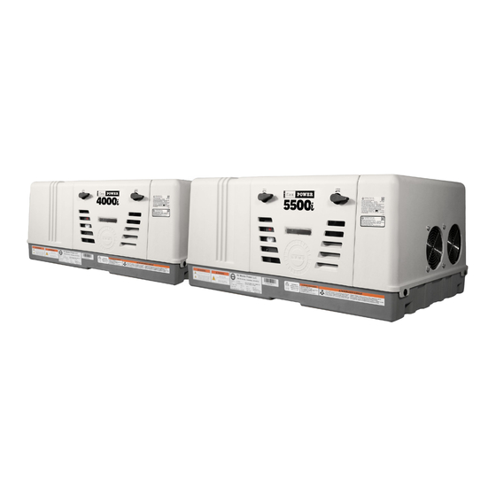
4000i & 5500i
INSTALLED GENERATORS
Authorized for installation ONLY in Recreational Vehicles prepped by the RV Manufacturer with fuel lines and a compartment
for permanent generator installs. Do NOT install in any other application without consulting a qualified professional.
Read this manual carefully before operation.
This manual includes important guidance for safety operation.
Visit rvmp.co • Copyright© 2023 RV Mobile Power, LLC. All Rights Reserved.
Advertisement
Table of Contents

Subscribe to Our Youtube Channel
Related Manuals for RVMP FLEX POWER 4000i


Summary of Contents for RVMP FLEX POWER 4000i
- Page 1 Do NOT install in any other application without consulting a qualified professional. Read this manual carefully before operation. This manual includes important guidance for safety operation. Visit rvmp.co • Copyright© 2023 RV Mobile Power, LLC. All Rights Reserved.
-
Page 2: Table Of Contents
Introduction Safety Precautions Troubleshoot Issue #1:Generator tries to start, some lights illuminate on the control panel, but generator will not start. 4 Check battery Check oil level Check spark plug circuit for adequate spark Check spark plug for damage Check proper function of fuel module, ECM, and inverter on 4000i Electrical Harnesses Fuel module Engine Control Module (ECM) - Page 3 Battery ground cable connection Ground posts Grounding jumper wire for mounting rack Troubleshoot Issue #3:Generator completely dead, does not attempt to start and no lights illuminate on control panel. 17 Check battery Check fuses Small fuel module fuse Larger inverter fuse for 4000i Larger inverter fuse for 5500i Troubleshoot Issue #4: Generator starts but runs rough when the breaker is OFF with no electrical load on the generator.
-
Page 4: Introduction
If you have any questions, please contact us at: RV Mobile Power, LLC Phone: (855) HAPPYRV Email: support@rvmp.co www.rvmp.co FIRE SAFETY NOTICE Keep multi-class ABC fire extinguishers handy. Class A fires involve ordinary combustible materials such as wood and cloth. - Page 5 ● Do not operate equipment when mentally or physically fatigued or after consuming alcohol or drugs. ● Do not use starting fluids which can cause an explosion and may result in death, serious personal injury and/or severe product and property damage. Do not use evaporative starting fluids. They are highly explosive.
-
Page 6: Troubleshoot Issue #1:Generator Tries To Start, Some Lights Illuminate On The Control Panel, But Generator Will Not Start
CAUTION The "CAUTION" symbol above is a sign that a procedure has a safety risk involved and may cause personal injury, product or property damage if not performed safely and within parameters set forth in this manual. ● Always wear eye protection when performing service, maintenance or installation procedures. Other safety equipment to consider would be hearing protection, gloves and possibly a full face shield, depending on the nature of the task. -
Page 7: Check Spark Plug Circuit For Adequate Spark
Check spark plug circuit for adequate spark Remove spark plug boot and unscrew spark plug from the engine with a spark plug socket. Re-attach the spark plug boot and carefully observe the spark plug gap while trying to start the generator. Be sure to stay clear of the spark plug gap and only observe for a spark with the naked eye. -
Page 9: Check Spark Plug For Damage
2. Output spark plug wire. Place one multimeter probe on the first conductor inside the harness and the other multimeter probe on the interior conductor of the spark plug boot. This measurement should be around 15,000 ohms. If the resistance is infinite, there is an open circuit failure and the ignition coil needs to be replaced. -
Page 10: Check Proper Function Of Fuel Module, Ecm, And Inverter On 4000I
Check proper function of fuel module, ECM, and inverter on 4000i Electrical Harnesses The 4000i requires electrical communication between the various components such as the fuel module, ECM, and the inverter in order to start and run properly. In some instances, it's possible that one of the electrical harnesses came unplugged through vibration or snagging when the cover was attached/replaced. -
Page 11: Inverter Cooling Fan Does Not Spin
power then it's likely the inverter is bad. This can also be checked by placing a multimeter on the two 120V AC output wires and see if there is proper voltage output. If not, the inverter is likely bad. Inverter cooling fan does not spin Additionally, there could be a failure in the inverter if the fan on the side of the inverter does not spin once the generator starts. -
Page 12: Inverter
Inverter Pull start test The 5500i uses the inverter to control the start sequence, so if the generator will not start it could be a bad inverter. To test for this, attempt to start the generator using the manual pull cord and listen for the fuel pump or the fuel solenoid ‘click.’... -
Page 13: Check For Vacuum Lock In The Gasoline Line
louder and/or makes a ‘clicking’ sound, there is either no fuel or a small amount of fuel getting into the fuel pump, and therefore some type of restriction in the gasoline line. Check for vacuum lock in the gasoline line If the generator will not start, check the gasoline lines for possible vapor lock. -
Page 14: Check Gasoline Solenoid On Carburetor
In some instances, this temperature sensor can fail, especially when exposed to very high ambient temperatures for a long period of time. Try unplugging the wire harness for the temperature sensor and see if the generator will start. If so, there is a failure in this temperature sensor and it needs to be replaced. DO NOT operate the generator without this temperature sensor or there will be no thermal protection for the generator if temperatures rise above the operational parameters and into a high temp damaging scenario which could damage various components of the generator permanently. -
Page 15: Check Fuel Pump
and that the issue must be within the specific gasoline supply components like the fuel pump, fuel tank, or fuel supply lines. Similarly, if the generator starts with gasoline but will not start with LP, then we know the issue likely has to do with the specific LP supply components like the regulator, gas solenoid, or LP supply. -
Page 16: Check Electrical Grounds
Similarly, if you are operating the generator while the RV is moving it is possible then when the RV goes up/down an incline or stops quickly, the oil in the pan can shift causing a low oil error which will stop the generator (if running) or prevent the generator from starting. -
Page 18: Grounding Jumper Wire For Mounting Rack
To mechanically check each post, conduct a ‘wiggle’ test by grasping one of the wires connected to the post or the post itself and attempt to wiggle the post. If either post is loose, tighten accordingly. To electrically check each post, use a digital multimeter placed on the resistance setting (Ω) to look for continuity: A) between a known ground on the chassis or battery and the first exterior post. -
Page 19: Troubleshoot Issue #3:Generator Completely Dead, Does Not Attempt To Start And No Lights Illuminate On Control Panel
for a faster installation when using the mounting rack, but care must be used to ensure the jumper wire is used and correctly installed. As shown above, a proper grounding jumper wire would connect its first end to the first exterior post on the generator and its second end to the negative battery cable post on the mounting rack. -
Page 20: Check Fuses
Check the battery for at least 450 CCA. For lead acid batteries, use a battery tester to measure the cold cranking amps (CCA) of the battery and ensure at least 450 CCA. For lithium batteries, ensure that the battery has a state of charge (SOC) of at least 25%. -
Page 21: Check For Bad Inverter
stepper motor contains a pair of mounting screws that can easily be removed to swap out the existing motor for a known operating motor. Check for bad inverter The inverter sends a digital signal to the stepper motor of the throttle to control the throttle depending on the electrical load of the generator. -
Page 22: Check Needle Jet For Dirt Or Obstructions
Check needle jet for dirt or obstructions Inside the carburetor is a needle jet for vaporizing gasoline prior to ignition. In some instances there can be dirt or other obstructions that may clog this jet and cause the generator to run rough or begin “hunting” where the RPMs of the engine change rapidly as the generator searches for the correct amount of throttle. - Page 23 4. Carefully remove the needle jet which is located directly underneath the idle adjustment screw. In most cases you can remove the needle jet by hand, but sometimes you may need to pry gently upwards on the needle jet with a flat head screwdriver to remove the needle jet. Be careful not to drop the needle jet into the bottom of the generator.
-
Page 24: Check Proper Setting On Altitude Adjustment
7. Re-install the idle adjustment screw with a phillips head screwdriver. DO NOT OVERTIGHTEN! The idle adjustment screw should be screwed in with little to no force, as the threads are plastic and could cross-thread. Carefully re-thread the screw into the hole and tighten until the screw is approximately halfway inside the hole. The idle adjustment screw if screwed all the way into the hole will increase the idle of the machine. -
Page 25: Clean Old Gas Or Buildup From Carburetor
generator at higher altitudes, you may experience rough running until the altitude adjustment is set to the correct level. If the generator is backfiring (running lean) turn the screw to the right to increase the altitude setting. If the generator is coughing or smoke is coming out of the exhaust (running rich) turn the screw to the left to decrease the altitude setting. -
Page 26: Check For Gasoline Vaporization Conditions
Check for gasoline vaporization conditions In some applications, the fuel line containing the gasoline can be located too close to other components on the RV that may heat up during operation (specifically the main exhaust for the RV chassis engine or the exhaust for the generator), where this heat can be transferred to the fuel line and eventually begin to vaporize the gasoline in the fuel line. - Page 27 It's imperative that these paths of air are kept separate and cannot mix with one another. If air from the hot outlet is ingested back into the cold air inlets, the generator will not be able to cool itself because it will be ingesting hot air back into the cooling inlets.
-
Page 28: Check For Gasoline Vaporization Conditions
Ensure plenty of fresh clean air is supplied into the cooling fan side of the generator (the right hand side where the large circular cold air inlets are shown), and nothing is blocking the cold air inlets to the generator. Further ensure that any compartment has adequate venting to allow fresh air into the compartment for cooling the generator. -
Page 29: Check For Vacuum Lock In The Gasoline Line
pump begin to get louder once there is no fuel or a small amount of fuel within the pump. If you hold down on the prime button and the fuel pump gets louder and/or makes a ‘clicking’ sound, there is either no fuel or a small amount of fuel getting into the fuel pump, and therefore some type of restriction in the gasoline line. -
Page 30: Instructions For Replacing Fuel Pump
Instructions for replacing fuel pump 1A. Locate the fuel pump and follow the fuel pump wires to the right until reaching the fuel pump wire harness (located just to the right of the inverter against the wall of the housing). Unplug the wire harness. If the harness cannot be reached or unplugged, see alternative method in Step 1B described below. - Page 31 back together with the new fuel pump. Locate the fuel pump and follow the fuel pump wires until reaching the fuel pump wire harness (located just to the right of the inverter). Unplug the wire harness (if reachable). 2. Locate the outlet hose coming from the fuel pump (the outlet hose is on the front side of the fuel pump, closest to the front door).
- Page 32 3. Slide the outlet hose off the fuel pump by hand or by placing a tool between the hose and the fuel pump and carefully prying/sliding the hose off the fuel pump.
- Page 33 4. Locate the worm clamp that wraps around the fuel pump and secures the fuel pump to the mounting bracket beneath the fuel pump. Use an 8 mm socket to loosen the clamp enough to slide off the mounting bracket below. 5.
- Page 34 6. Locate the brass elbow on the inlet side of the fuel pump and where it connects to the square fitting. Grasp the brass elbow with locking pliers while using a 9/16 inch open ended wrench to simultaneously grasp the square fitting. Unscrew the brass elbow from the square fitting.
-
Page 35: Instructions For Replacing The Fuel Filter
Instructions for replacing the fuel filter The following instructions are for replacing the fuel filter in a 4000i model generator. 1. Locate the fuel filter inside the front door and to the right of the airbox and above the fuel pump. 2. - Page 36 2. Loosen the bolt on the right hand side to remove the mounting strap from the inverter plate and remove the fuel filter from the mounting strap. 3. Remove the outlet hose clamp and remove the outlet hose from the fuel filter. 4.
-
Page 37: Instructions For Replacing The Carburetor
Instructions for replacing the carburetor The following instructions are for replacing the carburetor in a 4000i model generator. The process for replacing the 5500i is nearly identical, but there can be some variation to the images and exact location of some hoses. Otherwise the process for both the 4000i and the 5500i is the same. - Page 38 3. Locate and remove the air filter inside the airbox. 4. Locate and remove the metal plate behind the air filter. 5. Locate the mounting posts for the airbox and the nuts that secure the airbox to the posts. Remove the two (2) nuts with a 10 mm socket.
- Page 39 6. Locate and remove the large hose that connects to the top of the airbox. 7. Slide the airbox to the right and off the mounting posts. 8. Disconnect the small air hose from the airbox and remove the airbox completely from the generator housing.
- Page 40 9. Pay close attention to the air gasket plate located on the side of the carburetor between the carb and the airbox. This gasket plate can be removed at this point and kept for reassembly later, or it can be left in place until the carburetor is removed from the mounting posts later.
- Page 41 12. Remove the black cover at the top of the carburetor which covers the stepper motors that control the throttle and choke. The cover snaps on/off without any fasteners. 13. Slide the carburetor to the right, removing it from the two horizontal mounting posts. Remove and keep the airbox gasket plate (if not removed already in a prior step).
- Page 42 15A. Remove three (3) mounting screws from the motor plate which holds the throttle motor and choke motor. Once the mounting screws are removed, separate the plate and motors from the carburetor. 15B. Alternatively, if the mounting screws for the plate cannot be removed, remove two motor screws for each motor, four (4) screws total.
- Page 43 17. Use a flathead screwdriver (or similar) to pry the LP hose away from the carburetor. Slide the LP hose off the carburetor. 18. Use a pair of snips (or similar) to cut and remove the clamp which secures the gasoline hose to the carburetor. 19.
- Page 44 20. The old carburetor can now be completely removed from the generator. Perform steps 1 through 19 in reverse to install the new carburetor.
- Page 45 RV Mobile Power, LLC Phone: (855) HAPPYRV Email: support@rvmp.co www.rvmp.co Visit rvmp.co • Copyright© 2023 RV Mobile Power, LLC. - All Rights Reserved. v1.0.0...
Need help?
Do you have a question about the FLEX POWER 4000i and is the answer not in the manual?
Questions and answers
My 4000 09 generator on my 23 cross trails Coachman RV does not have the drain plug underneath like everybody says it should be there's nothing there but a big rubber washer and then when you take it off, there's no way to turn anything to drain all a little plastic tube comes down to drain your oil like you drain it from inside. Is that possible?
The RVMP FLEX POWER 4000i generator has an oil drain plug. The installation process mentioned modifications to ensure the oil drain had room, indicating that oil drainage is done through a drain plug.
This answer is automatically generated
@Mr. Anderson please show a photograph of the oil drain plug for RVMP Flex Power 4000i.
My 4000i is really slow at trying to start. The propane is good. The battery is 13.5v. Just doesnt sound like it wants to start.
@Robby It also doesn't seem like its rotating fast enough to get going. It wants to start on propane but its too slow
Is there an oil filter for the 4000? How much oil does it hold?
The available information does not mention an oil filter for the RVMP FLEX POWER 4000i. The oil capacity is 1.7 quarts (1.6 liters).
This answer is automatically generated
That's a 4000 onan generator no drain plug underneath like everybody says should be down there nothing but a big rubber washer cover something but you can't even turn it to get to it in a little plastic tube run down but the side of to drain your oil out. Need help here big time.