Table of Contents
Advertisement
Quick Links
Advertisement
Table of Contents

Related Manuals for Techno CNC Systems Titan NK105G3

Summary of Contents for Techno CNC Systems Titan NK105G3
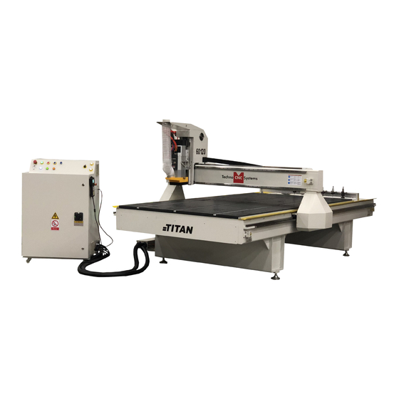
- Page 1 NK105G3 Titan Series Manual Techno CNC Systems, LLC ©2019 TITAN Series CNC Router Manual This document will provide a quick guide to the set up and operation of the Techno Titan Series CNC router equipped with the NCstudio G3 controller.
-
Page 2: Table Of Contents
NK105G3 Titan Series Manual TABLE OF CONTENTS Forklift Guide ............. Page 3 Safety Instructions ............. Page 4 Colleting Guidelines ............. Page 5 Techno Titan Series Quick Setup ........... Page 6 Techno Titan Series Installation ......Page 7 Vacuum Pump Installation ..........Page 10 Enabling the Titan Series .......... - Page 3 NK105G3 Titan Series Manual Techno CNC Systems Titan Series Forklift Guide LIFT TITAN FROM 1- a 5000LB CAPACITY OR LARGER FORKLIFT IS RECOMMENDED 2-ONLY LICENSED FORKLIFT OPERATORS SHOULD FRONT USE FORKLIFT 3-GREAT CARE MUST BE TAKEN WHEN LIFTING MACHINE TO PREVENT INJURY AND EQUIPMENT...
-
Page 4: Safety Instructions
NK105G3 Titan Series Manual Safety Instructions READ THESE INSTRUCTIONS THOROUGHLY BEFORE OPERATING MACHINE. DO NOT OPERATE MACHINE IF YOU ARE UNFAMILIAR WITH THESE SAFE OPERATING INSTRUCTIONS. DO NOT OPERATE MACHINE WITHOUT KNOWING WHERE THE EMERGENCY STOP SWITCH IS LOCATED. WARNING: IMPROPER OR UNSAFE OPERATION OF THE MACHINE WILL RESULT IN PERSONAL INJURY AND/OR DAMAGE TO THE EQUIPMENT. - Page 5 NK105G3 Titan Series Manual WARNING! THE SPINDLE WILL BE DAMAGED IF UNBALANCED EQUIPMENT IS USED. AIR SUPPLY MUST BE FILTERED AND DRY. Call: 1-631-648-7481 or Visit: support.technocnc.com...
-
Page 6: Techno Titan Series Quick Setup
NK105G3 Titan Series Manual I. TECHNO TITAN SERIES QUICK SETUP The Techno Titan Series CNC Router is powered by 220 Volt AC. Unless specially requested, the electronics require 3-phase power. Unpack the hand- The Electronics are housed in the large NEMA enclosure held controller as shown in Figure 1.1. -
Page 7: Techno Titan Series Installation
NK105G3 Titan Series Manual I.I Techno Titan Series Installation Carefully remove the Titan from its wood pallet. Be sure to remove the bolts from its four leveling feet insertion holes, as well as anything stowed under the Titan during shipping. Remove all bubble wrap, foam and strapping from the machine. - Page 8 NK105G3 Titan Series Manual Open the back of the controller box (shown in Fig 2.2a) with the key provided. The electronics will now be exposed and components identified in Fig 2.2b. A- Controller Board. B- 24Volt PSU. C- Stepper Driver. D- 220Volt In. Fig. 2.2b Fig. 2.2a Take the black connector coming from the Handheld controller (fig 2.3a,) and guide it through the hole in the side of the control cabi- net.
- Page 9 NK105G3 Titan Series Manual Have a qualified electrician attach 208-230 Volts, 3-phase to the terminal on the bottom of the box (Fig 2.4.) If the machine has been modified for single phase operation, then L1, L3 and GND are used, and nothing is attached to L2. Fig.2.4 If the machine has a vacuum table, the Vacuum Pump should be wired to 208- 230V, 3-phase or 440V (depending on what is specified on the Unit,) by a qualified...
-
Page 10: Vacuum Pump Installation
NK105G3 Titan Series Manual III. Vacuum Pump Installation 3 Phase Control Box Pump/Blower Motor Starter Box & Connector L1,L2,L3 NOTE: The cover was removed from Motor Starter. You will need to have the electrician connect AC power (208-230V 3PH) as specified on the unit to the Motor Starter at L1, L2, L3 and Ground (PE). Matching connector that will plug into the The starter box will have a round silver controller box (shown left) - Page 11 NK105G3 Titan Series Manual Make sure wire conduit is properly attached as shown in photos - any exposed wiring could be damaged and cause harm to the machine Make sure to attach a ground wire from the ground lug on the back of the machine to a grounding rod.
- Page 12 NK105G3 Titan Series Manual To check vacuum pump rotation and test on and off, first ensure power is connected to both the vacuum pump starter box as well as the controller cabinet. Once power is connected, turn the machine on by turning the main power disconnect switch to the vertical, “ON”, position. Power is now applied to the controller box. The red light on Power OFF will now light up indicating the machine is powered, but the controller and motors are not yet enabled.
- Page 13 NK105G3 Titan Series Manual Call: 1-631-648-7481 or Visit: support.technocnc.com...
-
Page 14: Enabling The Titan Series
NK105G3 Titan Series Manual IV. Enabling the Titan Series Machine Control Panel Functions Figure 4.1a shows the buttons and their functions. IMPORTANT: DOORS MUST BE CLOSED FOR POWER TO ENABLE. Fig. 4.1a Open/Close Emergency vacuum flow Stop Port Power Power Disable Enable Spindle Inverter Vacuum... - Page 15 NK105G3 Titan Series Manual 4.3 Titan Startup When the machine first powers on, the display on the controller will light up and say “Starting System”. (Fig. 4.1a) Once the system has booted it will ask the user “Back to reference point?” Fig 4.2b Fig. 4.1a Fig.
-
Page 16: Nk105G3 Controller
NK105G3 Titan Series Manual 5. NK105G3 Controller Handheld Controller Layout The layout of the NK105G3 handheld controller. Status Lights Execution Menu Keys & Navigation Keys Output Keys Movement Function Keys Keys Call: 1-631-648-7481 or Visit: support.technocnc.com... - Page 17 NK105G3 Titan Series Manual Single Keystroke Functions on the Handheld Pendant Call: 1-631-648-7481 or Visit: support.technocnc.com...
- Page 18 NK105G3 Titan Series Manual Movement Keys All the movement type keys are colored yellow. They will work in both Jog and Stepping modes. Call: 1-631-648-7481 or Visit: support.technocnc.com...
-
Page 19: Shift Commands / Combination Keystrokes
NK105G3 Titan Series Manual Shift Commands / Combination Keystrokes To use the shift commands, you must press and hold the shift key and then select a second key. When it reads X1 Y1 Z1, that is relative. When it reads X* Y* Z*, that means absolute. Call: 1-631-648-7481 or Visit: support.technocnc.com... -
Page 20: Execution Keys And Menu Navigation
NK105G3 Titan Series Manual Execution Keys and Menu Navigation Use the arrows to navigate menus, move cursors and in conjunction with other keys to perform specific functions. Status Lights and Indicators Spindle Chuck Controller Open / Close Power Dust Shroud Controller Alarm Pop Up Pins Up / Down Communication Running Call: 1-631-648-7481 or Visit: support.technocnc.com... -
Page 21: Operating Tutorials
NK105G3 Titan Series Manual 6. Operating Tutorials 6.1 - Switching Movement to Step or Jog. There are two modes that allow the user to control the movement of the machine: Jog and Step. To switch between these modes press the “Shift” button. -
Page 22: Modifying The Jog Speed And Step Size
NK105G3 Titan Series Manual 6.4 - Modifying the Jog Speed and Step Size The machine can be jogged at two speeds, low and high. You can also change the increments in which the machine will move in Step mode. These speeds are set in the Manual Parameters page. -
Page 23: Adjusting The Xyz Position/Wcs/User Origin
NK105G3 Titan Series Manual 6.6 - Adjusting the XYZ Zero position/WCS/User Origin XYZ zero position, Working Coordinate System (WCS), and User Origin are all the same thing. Different CAM systems and users just name the concept differently. For convenience, XYZ zero position will be used in the rest of this manual. XYZ zero position is the location point on a drawing in a CAD/CAM package where X,Y and Z all equal zero. -
Page 24: Loading A G-Code File
NK105G3 Titan Series Manual There are two methods for setting the Z-axis zero position: 1. Manual Method: Use the Z-axis directional arrows on the keypad to move the router to the top of the material. Switch to Step Mode to slowly move the machine into position. When the router bit is in position press shift/aux and the Z=0 button as shown. -
Page 25: Running A G-Code File
NK105G3 Titan Series Manual 6.8 - Running a G-code file Once the XYZ origin has been set as per section 6.6 and the file has been loaded as per section 6.7 the operator is now ready to run the G-code file. To run the G-code file simply press the start button Once the spindle has reached speed the machine will move into position to start the first cut. The file can be paused while running by pressing To resume the file press . To abort the file at any time press . Note: When the machine pauses, the spindle will stop and the Z axis will move to the Z clearance/ Safe height to allow inspection of the part. If the machine is jogged off the part during a pause, it will lose its position and when the file is resumed it will start from the new position. -
Page 26: Advanced Tutorials
NK105G3 Titan Series Manual 7. Advanced Tutorials 7.1 - Alternating between Override and Programmed Feedrates The controller can run G-code files with speed set by the user on the keypad, override speed, or with speed set in the CAM package/G-code file, programmed speeds. To determine what speed protocol will be used, do the following: In the main screen, press menu to enter the menu screen . 4. -
Page 27: Manually Changing Tools
NK105G3 Titan Series Manual 7.3 - Manually Changing Tools The Titan Series CNC Router is equipped with an HSD automatic Tool Changer spindle. This spindle allows the operator to save time by allowing the machine to change tools during a job, however, the operator may need to change tools manually. -
Page 28: 2- Using The Automatic Toolchanger Function
NK105G3 Titan Series Manual 7.3.2 - Using The Automatic Tool Changer Function Besides manually removing and inserting a tool into the spindle of the machine, you may tell the machine to drop off and pick up new tools in the linear rack. To perform an automatic tool change, first ensure that the tool clip for the tool currently in the spindle is empty and that there is a tool in the position you would like to change. Once these checks have been completed, you may now change tools. -
Page 29: 3- Tool Change Parameters And Settings
NK105G3 Titan Series Manual 7.3.3 - Tool Change Parameters and Settings The Titan Series CNC Router is shipped and set up with all tool change parameters pre-set. The operator may choose to change some of these settings. To find these settings, press “Menu” and then navigate to “4. Oper Params” and then “15. Tool Change” Call: 1-631-648-7481 or Visit: support.technocnc.com... -
Page 30: Setting Tool Lengths
NK105G3 Titan Series Manual 7.4 - Setting Tool Lengths To properly utilize the automatic toolchanger function of the Titan Series CNC router, the operater must measure and store the lengths of all the tools that the machine will be using. This process is easy and automated, with a few options depending on the operator’s needs. -
Page 31: How To Use The 6 Work Coordinates
NK105G3 Titan Series Manual 7.5 How to Use all 6 Work Coordinates This controller allows a user to have up to 6 work coordinates saved at a time. They are labeled as G54, G55, G56, G57, G58, and G59. The controller should be automatically set for G54 (work coordinate system 1) because next to X, Y and Z on the main screen should be a number 1. - Page 32 NK105G3 Titan Series Manual 7.6 How to Use the Select Line Number Function A file that is currently loaded to the machine may be ran using only certain line numbers of the G-Code if the operator chooses to do so. If the operator accidentally presses STOP, they can use this function to run from the last ran G-code line number (For ex: N100).
- Page 33 NK105G3 Titan Series Manual USING THE 4TH AXIS ON THE TECHNO TITAN MACHINES: Note: The 4th axis on the Techno Titan machine is not a true 4th axis. You can only use this to do “wrapping” tool paths. This means that the file is designed as a regular, flat, 3-axis file, which is scaled so that the width matches the circumference of round stock.
-
Page 34: Maintenance Information
NK105G3 Titan Series Manual 8. Maintenance Information The Techno Titan CNC Router will provide years of productive service if it is maintained properly. Based on a 40-hour work week, there are daily, weekly, monthly, quarterly, and yearly maintenance steps required for proper upkeep. -
Page 35: Lubricating The X-Y Rack And Pinion
NK105G3 Titan Series Manual 8.1 Lubricating the X-Y Rack and Pinion 8.3 Lubricating the Z Ballscrew Lubrication is important with rack and pinion The Z axis uses a ballscrew and ballnut instead gearing systems. A thin film of grease should of a Rack and Pinion. The ballnut has a nipple for always be present on the contacting tooth flanks to applying lubrication to the mechanism. -
Page 36: Parameter And Settings
NK105G3 Titan Series Manual Titan Settings 9. Parameter and Settings Website:support.technocnc.com | Call: 631-648-7481 Note: All settings with ‘*’ on screen requires reboot to take effect. LOCAL FILES USB FILES OPERATIONS Back to REF Point 1. All Home 2. Z Home 3. - Page 37 NK105G3 Titan Series Manual Titan Settings Website:support.technocnc.com | Call: 631-648-7481 Park Pos by [OK] Key Return by [ESC] Key Select WCS 1. G54 WCS 2. G55 WCS 3. G56 WCS 4. G57 WCS 5. G58 WCS 6. G59 WCS Array Process 1.
- Page 38 NK105G3 Titan Series Manual Titan Settings Website:support.technocnc.com | Call: 631-648-7481 3. 1 Point as 0* 4. Shape Process* 5. Bottom Process* 6. Metric Size* 13. ENG Params 1. Lifting Height* 2. Tool Change Tip* 3. Cycle Times* 4. Deep Hole Mode* 5.
- Page 39 NK105G3 Titan Series Manual Titan Settings Website:support.technocnc.com | Call: 631-648-7481 Z Down Option Z Plunge Cut Spd 12.000 in/min REF Circle Radius 5.0 inch REF Circle Speed 120.00 in/min Jump Speed 0.0 in/min LookAheadDis 0.0 in Axis Output Dir * (Varies by model) Pulse Equiv * (Varies by model)
- Page 40 NK105G3 Titan Series Manual Titan Settings Website:support.technocnc.com | Call: 631-648-7481 3. Initial Gear* 4. Max Spdl Speed* 24000 Y Rotary Axis 1. Y as Rotary Axis* 2. Rotary Y Pulse 3. MM as Unit 4. Rev Work Radius 5. Rotary Takeoff 6.
- Page 41 NK105G3 Titan Series Manual Titan Settings Website:support.technocnc.com | Call: 631-648-7481 System Update Register Help Reboot Exit Delete Log Disk Space 10. Delete Info 11. Modify Code Diagnosis 1. System Info Software Version Card No Remaining Time Register Times 2. Port List GX01 X-Origin GX02...
- Page 42 NK105G3 Titan Series Manual Notes On the G-code File If a part requires multiple tools, it is best to output a different file for each part. If the G-code file references a tool number higher than T10, then the controller will give an error at the start of the file. M6 T1 to M6 T10 are allowed. In general it is best to remove T commands by telling the CAM package that the machine is not a tool changer machine, or insuring that the Tool number does not exceed 10. G92 is the Axis presetting command, when this command is encountered in the G-code file the XYZ zero position is set at the position the machine is in at that time.
- Page 43 NK105G3 Titan Series Manual TLF 2.250-2.500 Internal Filter Inspection -Tools required- Flashlight ATTENTION Author: Mike Ruff Becker Pumps Corp. VISUAL CLUES REGARDING VTLF 2.250 FILTER MAINTENANCE SHOULD NOT ALWAYS BE THE SOLE INDICATOR OF WHETHER A FILTER IS “CLEAN”. THOUGH THE FILTER HAS TREMENDOUS SURFACE AREA, THE DEEP PLEATING OF THE FILTER MAY DISGUISE WHETHER THE FILTER IS CLOGGED.
- Page 44 NK105G3 Titan Series Manual -Remove the internal filter and look for debris- -Check for large debris deposits. This is an indicator that the filter caught the smaller particles- Author: Mike Ruff Becker Pumps Corp. -Use a flashlight on the outside of the filter- Author: Mike Ruff Becker Pumps Corp.
- Page 45 NK105G3 Titan Series Manual If light cannot be seen on the inside, the filter is clogged and needs replaced. Author: Mike Ruff Becker Pumps Corp. -If you can see light, then blow out the filter using compressed air and replace- •...
- Page 46 NK105G3 Titan Series Manual Greasing TLF 2.200-2.360 -Tools required- X1 – 7433050000 (50 gram grease gun) Author: Mike Ruff Becker Pumps Corp. Greasing instructions The greasing instructions can be found on step “P.” in the operation manual sent with each pump. Or they can be found at www.Beckerpumps.com Bearings are to be grease every 3000 –...
- Page 47 NK105G3 Titan Series Manual All new units come with new grease guns. (Found in either of the two places below) Author: Mike Ruff Becker Pumps Corp. GREASING PROCEDURE Author: Mike Ruff Becker Pumps Corp. Call: 1-631-648-7481 or Visit: support.technocnc.com...
- Page 48 NK105G3 Titan Series Manual Remove the filter cover by loosening the black hand knobs. Author: Mike Ruff Becker Pumps Corp. Remove the internal filter and replace if needed. Grease fittings are found next to the filter. (Remove the red caps.) Author: Mike Ruff Becker Pumps Corp.
- Page 49 NK105G3 Titan Series Manual Remove the black cap from the grease gun Author: Mike Ruff Becker Pumps Corp. Prime all new grease guns by placing them at an angle against a hard surface. Pump a few times until the grease is visible at the tip. Author: Mike Ruff Becker Pumps Corp.
- Page 50 NK105G3 Titan Series Manual Place the grease gun against the push fitting Pump 10x into each bearing (New or dry bearings = 25 times per bearing) Author: Mike Ruff Becker Pumps Corp. Once the pump is ran, the grease will evenly distribute between the rollers and ball bearings.
- Page 51 NK105G3 Titan Series Manual IX. Titan Troubleshooting Problem Solution Hand held controller display is blank with no Ensure the machine has power and is turned on. power Ensure that the 24V power supply has its green LED indicating it is on. Make sure the NK105 controller has power.
- Page 52 Limited Warranty On Techno Brand Products Subject to the terms and conditions set forth in this warranty document, Techno CNC Systems LLC (“Techno”) warrants its Techno brand products (“Product” or “Products”) to the original purchaser for a period of one (1) year against defects in material and workmanship under normal use and conditions (“Product Limited War-...
- Page 53 RESPECTIVE MANUFACTURER(S) OR SUPPLIER(S). Available warranties covering those components are furnished with each Product and Part. Techno CNC Systems does not assume any warranty obligation or liabil- ity for components covered exclusively by the stated warranty of a component’s respective manufacturer(s) or supplier(s).
- Page 54 * Use of non-standard parts or accessories without prior written approval from Techno. * Use of Product or part for purposes for which the item was not designed or intended. * Cancellation or recall of equipment/parts payment to Techno without specific prior written authorization from Techno.
- Page 55 Warranty inspections and repairs are performed at Techno’s New York facility, where all necessary diagnostic and repair equipment is available. This equipment is difficult to transport and field service is accordingly se- verely limited and will only be supplied at Techno’s sole discretion. If field service is required, all service call expenses, including transportation, travel time, subsistence costs, and the prevailing cost per hour (eight hour minimum) are the responsibility of the customer.
- Page 56 The terms and conditions contained herein shall constitute the entire agreement concerning the Limited War- ranty described herein. No oral or other representations are in effect. No dealer, distributor, or individual is authorized to amend, modify, or extend this Limited Warranty in any manner and only the warranty expressed in this warranty document is extended herein by Techno.
Need help?
Do you have a question about the Titan NK105G3 and is the answer not in the manual?
Questions and answers