Table of Contents
Advertisement
Quick Links
Advertisement
Table of Contents

Summary of Contents for SHAKTI PUMPS KUSPC 2.0
- Page 1 INSTALLATION & OPERATING INSTRUCTIONS KALPAVRIKSHA UNIVERSAL SOLAR PUMP CONTROLLER 2.0 SHAKTI PUMPS (INDIA) LIMITED Plot No. 401, 402, & 413, Industrial Area, Sector - 3, Pithampur - 454774, Dist. - Dhar, (M.P.) - INDIA, E-mail: info@shaktipumps.com, Visit us at : www.shaktipumps.com...
-
Page 2: Table Of Contents
PAGE NO. CONTENT CHAPTER 1: SAFETY INSTRUCTIONS..........Pre-Installation Safety Measures........Installation Safety Measures......... Safety during Operation..........Attention................... CHAPTER 2: INTRODUCTION............Product Overview............. Storage Instructions............Receiving and Inspection..........CHAPTER 3: PACKAGE CONTENTS..........05-06 CHAPTER 4: SPECIFICATIONS............CHAPTER 5: INSTALLATION............Mounting Method ............Installation Position............ -
Page 3: Chapter 1: Safety Instructions
INSTALLATION & OPERATING INSTRUCTIONS INSTALLATION & OPERATING INSTRUCTIONS CHAPTER 1 : SAFETY INSTRUCTIONS Ensure that the USPC, motor, and adjoining equipment are properly earthed to reduce electromagnetic emission and interference. 8. Unit must be earthed using appropriate wire size diameter and its WARNING! Ignoring the following instructions can cause physical injury or diameter should be equal to or higher than that input power supply damage to the equipment or death. -
Page 4: Product Overview
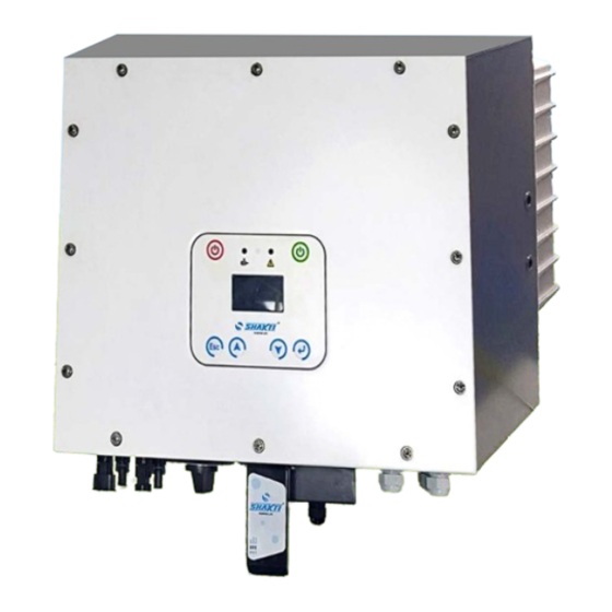
After receiving the drive, please check if the part no. indicated on the name plate corresponds with part no. of your order. Kalpavriksha Universal Solar Pump Controller (KUSPC 2.0) is a solar converter designed for maximum utilization of solar power available at the Serial Number Explanation site throughout the year. -
Page 5: Chapter 3: Package Contents
Ensure the optional parts are as per order, if ordered. Contact the customer care if there is any damage to the unit or the optional parts. J, K Fig. 3.2 Fig. 3.2 Images of list of Items in KUSPC 2.0 Packaging Table 3.1 List of Items Manufacturer S.No. Name Qty. -
Page 6: Chapter 4: Specifications
INSTALLATION & OPERATING INSTRUCTIONS INSTALLATION & OPERATING INSTRUCTIONS CHAPTER 4 : SPECIFICATIONS CHAPTER 5 : INSTALLATION KUSPC 2.0 Mounting Method, Installation Position and Mounting Procedure PARAMETERS 3 HP 5 HP 7.5 HP 10 HP of the USPC is illustrated as follows:... - Page 7 Place the mounting bracket using 4 screws STEP 2: Hold the unit gently & Fig. 5.3 Mounting Brackets for KUSPC 2.0 hook the unit to the wall mount brackets. Drill Holes and Place the Expansion Tubes According to the guides, drill 4 holes in the wall (in conformity with position marked in Figure 5.4 ) and then place expansion tubes.
-
Page 8: Chapter 6: Connections And Connecting Procedure
INSTALLATION & OPERATING INSTRUCTIONS INSTALLATION & OPERATING INSTRUCTIONS CHAPTER 6 : CONNECTIONS AND CONNECTING PROCEDURE 6.1. Rear Panel Rear Panel view without cover Rear Panel view with covers Fig. 6.1 Fig. 6.3 Rear Panel view with cover & Dongle Connected Table 6.1 Marking Description PV Input Connectors... - Page 9 INSTALLATION & OPERATING INSTRUCTIONS INSTALLATION & OPERATING INSTRUCTIONS 6.1.1 PV Input Connectors Table 6.2 Outside Diameter of the Cross - Sectional Area of Cables (mm ) Cables (mm) Scope Recommended Value 4.0-6.0 4.2 ~5.3 DC connector is made up of a positive connector and a negative connector as shown in figure 6.4 &...
- Page 10 The winding having voltage equal to the supplied voltage is the main winding. (nearly 230 V) KUSPC 2.0 provides a feature to operate three phase as well as single phase The other winding measuring voltage between 200-400 V is the Induction motors.
- Page 11 INSTALLATION & OPERATING INSTRUCTIONS INSTALLATION & OPERATING INSTRUCTIONS Fig 6.10a Connection diagram with cut-off switch connected to Aux winding Fig 6.11a Changeover switch connection corresponding to Fig 6.10a Fig 6.10b Connection diagram with cut-off switch connected to main winding The changeover switch connections are shown in Fig 6.11a and Fig 6.11b Fig 6.11b Changeover switch connection corresponding to Fig 6.10b Make sure that start capacitor does not come into picture when the motor is operated from KUSPC.
- Page 12 INSTALLATION & OPERATING INSTRUCTIONS INSTALLATION & OPERATING INSTRUCTIONS 6.1.5 Operation of KUSPC 2.0 with Single-phase Load: 6.1.7 SHAKTI RMS/IoT DONGLE Remote Monitoring and Control Single-phase load can be connected across thresher, aata chakki, chaff cutter or deep In-built Data Logger & RTC freezer.
- Page 13 INSTALLATION & OPERATING INSTRUCTIONS INSTALLATION & OPERATING INSTRUCTIONS Step3: To configure the Wi-Fi follow these steps:3.1) Turn ON Wi-Fi on your Mobile and select "SHAKTI_DONGLE and connect it with the password "shakti123". An HTML page will open in your browser otherwise browse http://192.168.4.1.
- Page 14 INSTALLATION & OPERATING INSTRUCTIONS INSTALLATION & OPERATING INSTRUCTIONS...
- Page 15 INSTALLATION & OPERATING INSTRUCTIONS INSTALLATION & OPERATING INSTRUCTIONS...
- Page 16 INSTALLATION & OPERATING INSTRUCTIONS INSTALLATION & OPERATING INSTRUCTIONS...
-
Page 17: Aux Input/Output & Rs485 Communication Connectors
INSTALLATION & OPERATING INSTRUCTIONS INSTALLATION & OPERATING INSTRUCTIONS 6.1.8. AC Output (v/f sinusoidal) There are at least 4 outputs of this category. The output voltages are 3 phase balanced sinusoids with constant flux control. These outputs can be configured via display, mobile application etc.. Any one output is functional at a time. Typical loads like Thresher, Aatta Chakki, Deep Freezer, Chaff Cutter etc. - Page 18 INSTALLATION & OPERATING INSTRUCTIONS INSTALLATION & OPERATING INSTRUCTIONS Aux Input Ports Normally, Pin-1 & 2 are closed and based on configuration, Pin-1 would connect with Pin-3. Aux Input port can trigger an event for the USPC by connecting Pin-1 & 3 by some external circuit or means. The events which can be triggered by Aux input port can be configured.
-
Page 19: Chapter 7: Operation Of Unit
INSTALLATION & OPERATING INSTRUCTIONS INSTALLATION & OPERATING INSTRUCTIONS CHAPTER 7 : OPERATION OF UNIT 7.1 Display Module Description Indiction LED 1 LED 1 Green (Motor) Green (Motor) Following figure 7.1 is indicates the outer look of Display. It has six buttons, Motor Running three LED indicators, one 128X64 pixel LCD Display. - Page 20 INSTALLATION & OPERATING INSTRUCTIONS INSTALLATION & OPERATING INSTRUCTIONS NOTE: The highlighted 5 compulsory parameters need to set before exiting the startup menu. Startup Main Menu SOLAR VFD MOTOR PUMP STATUS USPC MOTOR ENERGY & TIME TEMPERATURES MADE IN INDIA LIMIT VAR LANGUAGE LOCATION RTC DATE...
- Page 21 INSTALLATION & OPERATING INSTRUCTIONS INSTALLATION & OPERATING INSTRUCTIONS 4 STATUS 1 PV1 VOL 2 PV1 CUR 3 PV1 POW STATUS SOLAR 4 PV2 VOL A) SOLAR 5 PV2 CUR This status shows the real time PV condition of the system, such as input 6 PV2 POW 7 TOT POW voltage (V), input current (A), input power and cumulative energy (kWh).
- Page 22 INSTALLATION & OPERATING INSTRUCTIONS INSTALLATION & OPERATING INSTRUCTIONS CONTROL C) Language, Calender, Display These settings are used for configuring language, date, time & display A) ON/OFF settings. The device has an internal real time clock to remember date & Whenever ON option is selected the motor will turn on until it is turned off time settings even if solar power is not available.
-
Page 23: Chapter 8: Numerical Display Information
INSTALLATION & OPERATING INSTRUCTIONS INSTALLATION & OPERATING INSTRUCTIONS CHAPTER 8 : NUMERICAL DISPLAY INFORMATION The shakti display has got an unique feature that all the pages can be uniquely located with the use of words as well as numerals also. The location of pages wrt RETRY TIME numerals has a definite sequence as described below: Table 8.1.1 contains all parameters with their display number. -
Page 24: Display Information
INSTALLATION & OPERATING INSTRUCTIONS INSTALLATION & OPERATING INSTRUCTIONS 8.1.1 SR. NO. HEADING SR. NO. HEADING SR. NO. HEADING SR. NO. HEADING Display 3219 THERMAL DERATING Information MENU DISPLAY LOCK 37222 RATED PARAMETERS 321_10 MAX FREQ 3541 372221 RATED VOLTAGE 321_11 RETRY TIME STATUS 3542 3722211 MAINS VOLTAGE... -
Page 25: Chapter 9: Troubleshooting
INSTALLATION & OPERATING INSTRUCTIONS INSTALLATION & OPERATING INSTRUCTIONS SR. NO. HEADING SR. NO. HEADING SR.NO. HEADING SR. NO. HEADING CONTROL PARAMETERS 3741 WATER PUMP 372521 RATED VOLTAGE 37464 LOGS 37411 TORQUE BOOST PER 3725211 MAINS VOLTAGE 37465 WC MOD VDC FAULT LOGS 37412 RAMP TIME PMSM... - Page 26 INSTALLATION & OPERATING INSTRUCTIONS INSTALLATION & OPERATING INSTRUCTIONS...
-
Page 27: Chapter 10: Recycling & Disposal
INSTALLATION & OPERATING INSTRUCTIONS INSTALLATION & OPERATING INSTRUCTIONS CHAPTER 10 : RECYCLING & DISPOSAL Electrical & electronic waste should not be thrown out in open or buried or fired. They must never be treated as residential waste. A unit which was reached end of its life or is not needed any more should be returned to the dealer or to the company. -
Page 28: Warranty Certificate
Country ....................service for twelve months from the date of purchase by the first user. Pin Code ....................Shakti Pumps (India) Limited warrants this product to be free from damage/ Mobile no..................... Email id ....................defects in material and workmanship under normal use and service for Twelve Months from the date of purchase by the first user. - Page 29 INSTALLATION & OPERATING INSTRUCTIONS BOOK-POST Stamp SHAKTI PUMPS (INDIA) LIMITED Plot No. 401, 402, & 413, Industrial Area, Sector - 3, Pithampur - 454774, Dist. - Dhar, (M.P.) - INDIA. Toll Free. 1800 103 5555 E-mail : info@shaktipumps.com, sales@shaktipumps.com Visit us at : www.shaktipumps.com...
Need help?
Do you have a question about the KUSPC 2.0 and is the answer not in the manual?
Questions and answers