
Summary of Contents for GT LASERS CYL-2000/S
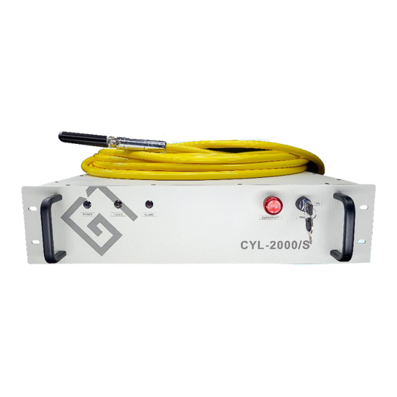
- Page 1 CYL-2000/S 1.0μm Single Mode Continuous Fiber Laser User manual ZHEJIANG GT LASERS TECH.CO., LTD.
- Page 2 Direct or indirect use of the information provided in this manual does not mean that GT Lasers authorizes any patent or other intellectual property. Zhejiang GT Lasers Tech. Co., Ltd. All rights reserved. This content is not allowed to be reproduced, transmitted, stored, or adapted for publication in any form or method without...
-
Page 3: Table Of Contents
Contents 1.0 Safety Information ................4 1.1 Security identity ........................4 1.2 Laser safety level ........................ 5 1.3 Optical security ........................5 1.4 Electrical security ........................ 5 1.5 Other safety precautions ..................... 5 2.0 Description of Product ............... 5 2.1 Product characteristics ......................5 2.2 Product advantage ....................... -
Page 4: Safety Information
1.0 Safety Information Thank you for choosing GT Lasers fiber laser, this user manual provides you with important safety, operation, maintenance, and other information. Therefore, please read this user manual carefully before using this product. We will use different words and characters to alert you to potential hazards and important information, including: 1.1 Security identity... -
Page 5: Laser Safety Level
Please strictly follow the laser manual to operate the laser, otherwise any damage to the laser will not be guaranteed. The laser does not have built-in usable accessories, all repairs should be carried out by GT Lasers technicians. To prevent electric shock, please do not damage the label or remove the lid, otherwise any damage to the laser will not be guaranteed. -
Page 6: Product Advantage
GT Lasers with its high quality, high reliability and excellent cost performance, can meet the diverse needs of customers, customization and good after-sales service, which is an ideal choice for system integrators and equipment manufacturers. -
Page 7: Order Information
Communication interface RS232/AD /Super terminal Remote communication Customizable Power supply CYL-1000/S Single phase three CYL-1500/S Power (KW) consumption CYL-2000/S 220 V in two groups CYL-3000/S Cooling mode Water cooling External Cooling water temperature (° C) CYL-1000/S CYL-1500/S Cooling water (L/min) -
Page 8: Product Installation
Once the external box is found to be abnormal, please inform GT Lasers in time so that we can deal with it as soon as possible. After unpacking, please check whether the packing list is consistent with the actual items. If in doubt, please contact GT Lasers in time. -
Page 9: Product Performance
CAUTION: do not expose this product to a high humidity environment (humidity >95%). Do not let this product work below the dew point temperature. (As Table below) Constant dew point table at ambient temperature and relative humidity Maximum relative humidity Ambient 20% 30% temperature ℃... -
Page 10: Notes
3.5 Notes Before connecting the laser to the AC power supply, ensure that it is connected to 220V voltage, wrong connection to the power supply will cause irreparable damage to the laser. It is very important to ensure that the output end of the adjusted laser output head is clean, otherwise the laser will be irreparably damaged. -
Page 11: Precautions For The Cooling System
The minimum bending diameter of the transmission fiber of the laser should not be less than 20cm in the non-working state such as transportation and storage; the minimum bending diameter should not be less than 30cm in the laser emitting state. CAUTION: all control lines of the lasers should be connected in a non-electric state, and the live installation of control lines may cause laser damage. -
Page 12: Use Of Products
Water cooling requirements for output cables: Cooling water flow: 1.7-2.0L/min Water cooling pressure: inlet less than 0.6Mpa Water pipe type: outer diameter ϕ6 inner diameter ϕ4 Cooling water direction: unidirectional, connect the water pipe in strict accordance with the water inlet and outlet direction marked on the shell. -
Page 13: Rear Panel Of The Product
Use the key switch to power on the laser to back to normal. 4.2 Rear panel of the product AC INPUT: AC power input socket, must be used with the plug provided by GT Lasers. This socket has a lock. SERVICE:... - Page 14 4.3 Control interface definition DB15 Control Interface Diagram DB25 pin is defined as follows: Pin NO. Definition Remarks Remote control light, front panel red indicator light up. 1(EN+) (5-24V) Emission enable 2(EN-) (0V) 18(PWM+) (5-24V) Modulated signal input 19(PWM-) (0V) Return 20(DA+) (0-10V)...
-
Page 15: Power Connection
Note: please check the level of the control signal to ensure compliance. Voltage excess or voltage fluctuation may damage the laser. Ensure that the analog voltage signal does not exceed 10V, otherwise the laser may be damaged. Control signal line All the control signals of the laser are concentrated on the control signal (DB25 interface) port of the rear panel. - Page 16 Power outlet The other end of the power supply is a stripped four-strand wire, which marks as, L1, L2, N and PE. It can be connected to two groups 220V AC power supply according to the wire mark. The power cord must be reliably connected as shown in the table before the laser is powered on.
-
Page 17: Control Interface Definition
The power cord provided by our company: Insert the plug at the end of the power supply into the AC power interface on the rear panel. Note that the plug has an anti-reverse connection function. CAUTION: please check the level of the control signal to make sure it meets the requirement. - Page 18 Steps : Please turn on the computer and insert the U disk, as shown in the figure: click the PL2303 folder, double-click to install the driver. One end of the RS232 line is connected to the RS232 interface on the rear panel of the laser, and one end is connected to the USB interface on the PC.
- Page 19 Double-click GT Fiber Laser Control System V1.23 (laser control software). Click Refresh , select the corresponding port and connect. QCW mode: the optical laser can produce pulse of μs magnitude, duty cycle is 10%. This allows the pulsed light to have a peak power of more than ten times the average power, which is very beneficial for applications such as drilling.
-
Page 20: Quality Assurance And Repair And Return Process
Unless otherwise specified, GT Lasers provides a 24-month warranty for all products for material defects and quality problems (from the date of shipment). GT Lasers will choose 1) repair 2) replace 3) refund products that are confirmed to be defective and still within the warranty period.
Need help?
Do you have a question about the CYL-2000/S and is the answer not in the manual?
Questions and answers