
Summary of Contents for SPARQ Q2000
- Page 1 The Q2000 Microinverter Installation Manual for India Model Q2000-4102 Document revision 1.2...
- Page 2 Contact Information: SPARQ Systems Inc. Innovation Park, Box 212, 945 Princess St., Kingston, Ontario CANADA K7L 0E9 P: 1-343-477-1158 support@sparqsys.com www.sparqsys.com FCC Compliance: This product has been tested and was found to be compliant with the accepted limits for a Class B digital device, pursuant to part 15 of the FCC Rules.
- Page 3 EVISIONS Version Date December 2022 March 2023 April 2023...
-
Page 4: Table Of Contents
ABLE OF ONTENTS READ THIS FIRST ............................6 1. INTRODUCTION ............................8 1.1. What is a SPARQ Microinverter ......................9 1.2. System Configuration and Monitoring ..................... 9 2. SPARQ MICROINVERTER INSTALLATION DESIGN ................10 2.1. Preparation ............................. 10 2.2. PV module and Microinverter Compatibility .................. 10 2.3. - Page 5 3.11. Protection Against Lightning Surges .................... 31 3.12. Electrical Wiring Diagram ......................31 SparqVu ............................... 33 4.1. Creating a new SparqVu account ....................33 4.2. Adding a new SparqLinq site to your SparqVu account ............... 34 4.3. Accessing a SparqVu project’s /System page ..................35 4.4.
-
Page 6: Read This First
(certified installers or electricians) shall install or replace the SPARQ Microinverter. Be aware that installation of this equipment includes the risk of an electric shock. • Do not install the AC junction box without first removing AC power from the SPARQ System. - Page 7 The Q2000-4102 can operate at locations with an ambient temperature between -40ᴼC and 65ᴼC (-40ᴼF to 149ᴼF). The DC voltage range of a PV module to be used with the SPARQ Q2000 Microinverter should be between 19 and 60V. This matches most 60 cell and 72 cell modules.
-
Page 8: Introduction
The Q2000 has the most advanced power conversion design in the industry today. It is the first microinverter on the market with reactive power capability, designed to meet the new interconnection, operation and metering requirements for distributed generators to be connected to a utility’s electric system now. -
Page 9: What Is A Sparq Microinverter
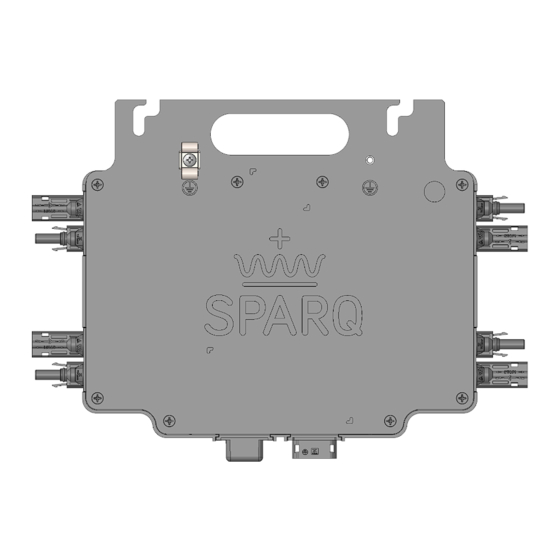
Installation & Setup 1.1. What is a SPARQ Microinverter The SPARQ Q2000 microinverter is a power conversion device that connects to up to four photovoltaic (PV) modules and converts the DC output of the modules into grid-compliant AC power. PV systems that... -
Page 10: Sparq Microinverter Installation Design
The SparqLinq internal web server and SparqVu cloud-based server enable an installer or system owner to quickly view the performance of every component of their SPARQ energy system via a web browser on their smart device or computer. SparqLinq achieves this detailed performance tracking by periodically polling all microinverters with a typical polling cycle of five minutes. -
Page 11: Module System Design Configuration With Templates
DC inputs. Alternate configurations can easily be supported via extension cables. SPARQ has created simple templates for each of these designs. In some cases, where the standard building blocks are not applicable, an extender cable may be required to ensure easy connectivity to the Q2000 microinverter. -
Page 12: Row Of Four
Connect modules 1 and 2 first and connect them to the racking. Then connect the module 4 but do not tighten it, instead rest it in a temporary and stable position. Then connect the one under module 3 over the Q2000 and connect it to the rack. Last, place the module #4 in its permanent position, tightening it last. -
Page 13: T-Shape
2.3.5. S-Shape A final standard shape to help make things fit in unusual configurations, an S-Shape solution can be useful in either landscape or portrait mode as shown below: SPARQ Q2000 Microinverter Installation Manual – Version 1.1, March 2023 Page 13... -
Page 14: Accessories
The system must be installed by Rooftop Solar specialists. It is critical that the system is designed and approved by a certified electrical authority in your jurisdiction. After the racking system is installed, it is relatively easy to install the Q2000 and the PV modules on the racking. To do so, the following steps are required: •... -
Page 15: Sparqlinq Configuration
A technician can start setting up the SparqLinq gateway for the site at any time but Q2000 microinverters can only be scanned once the Q2000 is connected to a PV Panel and in the daytime when there is enough sun to power the Q2000. - Page 16 This is the default IP address of the SparqLinq. Note: See the Troubleshooting section for suggestions on connecting to the Linq via Ethernet only (that is, without using the WiFi adaptor). SPARQ Q2000 Microinverter Installation Manual – Version 1.1, March 2023 Page 16...
-
Page 17: Software Updates
If “Apply Update” button is highlighted, select this option, and wait till the SparqLinq update is completed. This could take a few minutes as it is dependent on the speed of the internet connection. SPARQ Q2000 Microinverter Installation Manual – Version 1.1, March 2023 Page 17... -
Page 18: Technician & Customer Information
SparqVu dashboard. • City, State Figure 10: Inverter detection. Select “Next Step: Inverter Configuration” to identify and configure the Q2000 microinverters that have been installed. 3.1.4. Inverter Configuration Inverter configuration begins with the “scanning” activity, wherein, the SparqLinq surveys the nearby radio environment listening for any Q2000 microinverters who are generating power as shown in Figure 11. - Page 19 Once an Inverter has been found, it will stay connected to the SparqLinq even after the SparqLinq is moved back to the starting position. SPARQ Q2000 Microinverter Installation Manual – Version 1.1, March 2023 Page 19...
-
Page 20: Network Configuration
Click on the menu icon (three horizontal bars) in the top left corner of the dashboard page and then select the Settings option as shown in Figure 14. SPARQ Q2000 Microinverter Installation Manual – Version 1.1, March 2023 Page 20... - Page 21 SparqLinq access point unless “Connect Automatically” was set on the installer’s device. If the test was successful, the following screen will be displayed as shown in Figure 16. SPARQ Q2000 Microinverter Installation Manual – Version 1.1, March 2023 Page 21...
- Page 22 After the network settings is established, you will see a screen like Figure 17. Please note the IP address for accessing SparqLinq. Click on the “Go to the Dashboard” button. You will be redirected to the SparqLinq Dashboard. Your setup is now complete! SPARQ Q2000 Microinverter Installation Manual – Version 1.1, March 2023 Page 22...
-
Page 23: Microinverter Placement And Installation
There is a handle in between these mounting slots for ease of carrying and placement of the Q2000s around the job site and on the roof top. Use two fasteners to mount the Q2000 to the rail and torqued to 10 ft-lbs / 13.5 N-m. -
Page 24: Cabling System
SPARQ has partnered with Ti-Lane to bring you a complete cabling solution that makes installing the SPARQ microinverters snap. This mature and robust solution ensures an easy and cost-effective deployment of your SPARQ system. These cables come with the AC connector ready to be plugged into the SPARQ microinverter. - Page 25 AWG (6mm²) homerun cable will have a lower overall cable resistance resulting in less voltage drop along the cable, so it may also be used in long cables with less than three Q2000 microinverters installed. Do not exceed the recommended number of microinverters per trunk cable as noted above.
-
Page 26: Cable Accessories
Secure Junction Boxes with cable ties or other reliable method. Step 4: Align the mating AC connectors and join mating parts together as shown below and connect the AC plugs. SPARQ Q2000 Microinverter Installation Manual – Version 1.1, March 2023 Page 26... - Page 27 IP67 sealing to avoid risks of electrical shock and short circuits when the system is energized. Cable Disassembly Instructions To unlock the T5 cable connectors from the inverter bulkhead, use the AC unlocking tool. The unlocking SPARQ Q2000 Microinverter Installation Manual – Version 1.1, March 2023 Page 27...
-
Page 28: Ti-Lane Cable Part Number Information
T6 tee male to open Part Number 2C/10AWG 65012-02 65012-03 T6 cross male to open Part number 2C/10AWG 65014-11 65014-12 * The color coding for India is Line: Brown, and Neutral: Blue. SPARQ Q2000 Microinverter Installation Manual – Version 1.1, March 2023 Page 28... -
Page 29: Mounting The Sparq Microinverter
For the 4 module that will cover the Q2000, rail clips should be used to hold the excess cable from the module to the Q2000 (as opposed to module frame clips). 2. With one person or suitable fixture/support holding the module up, connect the module’s MC4- compatible connectors to the... -
Page 30: Ac Connection
The illustration below shows how to make the grounding bond to the microinverter using microinverter ground lug. This is a side view of the grounding clip installed on the Q2000. This grounding lug is internally bonded to the microinverter ground screw and provides a high-level of ground bond between the microinverter enclosure and the system ground. -
Page 31: Protection Against Lightning Surges
Figure 27 shows the Q2000 attached to a mounting rail with a solid copper conductor attached to the grounding clip as well as the WEEB grounding method. - Page 32 Installation & Setup Here is a typical electrical wiring diagram showing the main parts of a SPARQ Q2000 system for use with a residential 220/230V single-phase electrical service. It should be noted that in case of paralleling multiple microinverters, the proper size of the trunk cable and the circuit breaker must be utilized. For instance, a 6 mm (AWG 10) trunk cable can handle up to three microinverters with a 30A circuit breaker.
-
Page 33: Sparqvu
Figure 29: Single line diagram for three phase system. SparqVu SPARQ offers complete system management for initial installation as well as ongoing monitoring of the SPARQ System production and performance. Named “SparqVu”, it offers a mobile friendly, easy to use solution for installers and end customers. -
Page 34: Adding A New Sparqlinq Site To Your Sparqvu Account
Enter the full email address that was used to create the SparqVu account and click “Generate Access Token” and copy the Token value. Click on the “Activate on SparqVu” button and login to your account. SPARQ Q2000 Microinverter Installation Manual – Version 1.1, March 2023 Page 34... -
Page 35: Accessing A Sparqvu Project's /System Page
The /System page can allow installers to view customer and installation information. It also provides a way to remotely initiate a GFDI reset by clicking the [Clear GFDI] action. SPARQ Q2000 Microinverter Installation Manual – Version 1.1, March 2023 Page 35... - Page 36 Figure 35: SparqLinq system page. Clicking on an microinverter serial number allows additional information to be displayed regarding that specific inverter and its modules. Figure 36: Inverter detailed information. SPARQ Q2000 Microinverter Installation Manual – Version 1.1, March 2023 Page 36...
-
Page 37: Documenting The Module Inverter Connections During Installation
4.4. Documenting the module inverter connections during installation As you design the system, SPARQ has included easy stickers to be mapped into your design. They allow the ability to identify which module is connected to which port, and which module has the Q2000 underneath it should any troubleshooting need to take place in the future. - Page 38 Once logged in, the installer will be able to see all of the sites they are registered to manage. This is called the Project Selection page and is designed for when you are managing the 2 customer and beyond: Figure 39: Navigating sites. SPARQ Q2000 Microinverter Installation Manual – Version 1.1, March 2023 Page 38...
-
Page 39: Generating Power
Check all connections to make sure they are fully connected, and no wires are damaged or pinched. □ Confirm all microinverters are grounded using a grounding wire or by using the appropriate grounding washer for your racking. SPARQ Q2000 Microinverter Installation Manual – Version 1.1, March 2023 Page 39... -
Page 40: Troubleshooting
SparqLinq communication related conditions. There is also a magnetic field sensor that allows the Q2000 to be manually released by placing a magnet next to the plastic LED bezel. The LEDs and the magnetic sensor spot are shown in the diagram below. -
Page 41: Communication Status Led Indication Table
Move the SparqLinq closer to the inverter network is missing. Normal operation Flashing Ready to join network. Run the SparqLinq setup wizard to join the inverter to the SparqLinq RED/AMBER SPARQ Q2000 Microinverter Installation Manual – Version 1.1, March 2023 Page 41... -
Page 42: Power Status Led Indication Table
Ground fault detector Please contact SPARQ for support WARNING: No attempt should be made to repair the SPARQ Microinverter; there are no user serviceable parts. By opening the microinverter you risk voiding your warranty. If the device fails, please contact SPARQ customer service. -
Page 43: Inverter Management
The settings page becomes available accessible after the configuration wizard completes. Connect to the SparqLinq and select the settings page from the menu: Figure 42: SparqLinq Menu. Click the Inverter Management Tab: Figure 43: SparqLinq Settings tab. SPARQ Q2000 Microinverter Installation Manual – Version 1.1, March 2023 Page 43... -
Page 44: Releasing An Inverter
The inverter will Ask to confirm or cancel this action. Figure 45: GFDI release. After the inverter has been released, it will be removed from the list: Figure 46: Removing an Inverter. SPARQ Q2000 Microinverter Installation Manual – Version 1.1, March 2023 Page 44... -
Page 45: Adding An Inverter
If a Q2000 has been joined to a SparqLinq, it can be manually released by placing a magnet next to the plastic LED bezel. This will allow it to be joined to a new SparqLinq. 5.2.3. Adding an Inverter From the inverter management tab, click on the ‘Add Inverters’ button: Figure 47: Adding an Inverter. -
Page 46: Clearing The Gfdi (Ground Fault Detection Interruption) Condition
GFDI flag. This is done through the inverter management screen. Click on the blue lightning bolt to initiate clearing the GFDI flag. SPARQ Q2000 Microinverter Installation Manual – Version 1.1, March 2023 Page 46... - Page 47 Once you have determined the SparqLinq’s local IP address, type it in the browser’s address bar to connect to the Dashboard or Wizard. In the example below you would type in the following: http://192.168.0.5/ . SPARQ Q2000 Microinverter Installation Manual – Version 1.1, March 2023 Page 47...
-
Page 48: Disconnecting The System
Bulkhead connectors are used for DC inputs and AC output. Landscape and Portrait Installation — Indicates whether the long side of the PV modules are oriented horizontally (landscape) or vertically (portrait) in the array. SPARQ Q2000 Microinverter Installation Manual – Version 1.1, March 2023 Page 48... -
Page 49: Ti-Lane Cable Specification
11.2. Standalone operation The SPARQ Q2000 microinverter can be used in the standalone applications where the AC power grid is not available. The installation process is the same as described above in this operating manual. The user SPARQ Q2000 Microinverter Installation Manual – Version 1.1, March 2023... -
Page 50: Datasheet
Less than 200ms Frequency Trip Time Regulatory UL1741, UL1741 SA/Rule 21/HECO/Rule 14H, IEEE1547, IEEE1547.1, CSA22.2 No. 107.1, FCC Part 15-Class B. Regulatory Certifications IEC62109-1:2010, IEC 62109-2:2011, IEC 61000-6-3:2007 SPARQ Q2000 Microinverter Installation Manual – Version 1.1, March 2023 Page 50... - Page 51 Programmable on both active and reactive power Volt-VAR Programmable VAR injection and power factor limit Programmable active power curtailment with an Frequency-Watt adjustable rate of Watt per Hz SPARQ Q2000 Microinverter Installation Manual – Version 1.1, March 2023 Page 51...
Need help?
Do you have a question about the Q2000 and is the answer not in the manual?
Questions and answers