Table of Contents
Advertisement
SERVICE MANUAL
TECHNICAL INFORMATION
FOR SERVICE PERSONNEL ONLY
RAK-60PPA
SPECIFICATIONS
TYPE
MODEL
POWER SOURCE
TOTAL INPUT
TOTAL AMPERES
COOLING
CAPACITY
TOTAL INPUT
TOTAL AMPERES
HEATING
CAPACITY
DIMENSIONS
(mm)
NET WEIGHT
SPECIFICATIONS AND PARTS ARE SUBJECT TO CHANGE FOR IMPROVEMENT
ROOM AIR CONDITIONER
FEBRUARY 2013
RAC-60WPA
INDOOR UNIT
RAK-60PPA
(W)
(A)
(kW)
(B.T.U./h)
(W)
(A)
(kW)
(B.T.U./h)
W
H
D
(kg)
INDOOR UNIT + OUTDOOR UNIT
Refrigeration & Air-Conditioning Division
PM
RAK-60PPA/RAC-60WPA
REFER TO THE FOUNDATION MANUAL
SPECIFICATIONS ------------------------------------------------------ 5
HOW TO USE ---------------------------------------------------------- 7
CONSTRUCTION AND DIMENSIONAL DIAGRAM ---------44
MAIN PARTS COMPONENT --------------------------------------46
WIRING DIAGRAM ---------------------------------------------------48
CIRCUIT DIAGRAM --------------------------------------------------49
PRINTED WIRING BOARD LOCATION DIAGRAM --------55
BLOCK DIAGRAM ----------------------------------------------------58
BASIC MODE ----------------------------------------------------------59
REFRIGERATING CYCLE DIAGRAM---------------------------77
AUTO SWING FUNCTION -----------------------------------------78
DESCRIPTION OF MAIN CIRCUIT OPERATION -----------79
SERVICE CALL Q & A ----------------------------------------------93
TROUBLE SHOOTING ----------------------------------------------97
PARTS LIST AND DIAGRAM ------------------------------------ 123
(WALL TYPE)
1 PHASE, 50/60 Hz, 220-240V
1,850 (155 - 2,300)
8.50 - 7.80
6.10 (0.9 - 6.5)
20,820 (3,070 - 22,190)
1,880 (155 - 2,550)
8.60 - 7.90
6.80 (0.9 - 8.5)
23,210 (3,070 - 29,000)
1030
295
207
12
NO. 0540E
CONTENTS
OUTDOOR UNIT
RAC-60WPA
850
650
298
45
After installation
Advertisement
Table of Contents

Related Manuals for Hitachi RAC-60WPA


Summary of Contents for Hitachi RAC-60WPA
-
Page 1: Table Of Contents
NO. 0540E RAK-60PPA/RAC-60WPA SERVICE MANUAL REFER TO THE FOUNDATION MANUAL TECHNICAL INFORMATION FOR SERVICE PERSONNEL ONLY CONTENTS SPECIFICATIONS ------------------------------------------------------ 5 HOW TO USE ---------------------------------------------------------- 7 CONSTRUCTION AND DIMENSIONAL DIAGRAM ---------44 MAIN PARTS COMPONENT --------------------------------------46 WIRING DIAGRAM ---------------------------------------------------48 CIRCUIT DIAGRAM --------------------------------------------------49... - Page 2 SAFETY DURING REPAIR WORK 1. In order to disassemble and repair the unit in question, be sure to disconnect the power cord plug from the power outlet before starting the work. 2. If it is necessary to replace any parts, they should be replaced with respective genuine parts for the unit, and the replacement must be effected in correct manner according to the instructions in the Service Manual of the unit.
- Page 3 WORKING STANDARDS FOR PREVENTING BREAKAGE OF SEMICONDUCTORS 1. Scope The standards provide for items to be generally observed in carrying and handling semiconductors in relative manufacturers during maintenance and handling thereof. (They apply the same to handling of abnormal goods such as rejected goods being returned). 2.
- Page 4 (6) Use a three wire type soldering iron including a grounding wire. Metal plate (of aluminium, stainless steel, etc.) Working table Resistor of 1 M (1/2W) Staple Earth wire Bare copper wire (for body earth) Fig. 3. Grounding of the working table Soldering iron Grounding wire Screw stop at the screwed...
- Page 5 CAUTION In quiet or stop operation, slight fl owing noise of refrigerant in the refrigerating cycle is heard occasionally, but this noise is not abnormal for the operation. When it thunders near by, it is recommend to stop the operation and to disconnect the power cord plug from the power outlet for safety.
-
Page 6: Specifications
SPECIFICATIONS MODEL RAC-60WPA RAK-60PPA FAN MOTOR 47 W 38 W FAN MOTOR CAPACITOR FAN MOTOR PROTECTOR – COMPRESSOR JU1015D9 COMPRESSOR MOTOR CAPACITOR OVERLOAD PROTECTOR YES (INTERNAL) OVERHEAT PROTECTOR 3.15A FUSE (for MICROPROCESSOR) 3.15A POWER RELAY POWER SWITCH TEMPORARY SWITCH TEST/SERVICE SWITCH... - Page 7 Figure showing the installation of Indoor and Outdoor unit Be sure to completely seal any gap The indoor piping should be insulated with the enclosed insulation pipe. (If the insulator is insufficient, please use commersial products). The difference in height ●...
- Page 8 SAFETY PRECAUTION ● Please read the “Safety Precaution” carefully before operating the unit to ensure correct usage of the unit. ● Pay special attention to signs of “ Warning” and “ Caution”. The “Warning” section contains matters which, if not observed strictly, may cause death or serious injury.
- Page 9 PRECAUTIONS DURING OPERATION ● not for any other intended use. Do not attempt to operate the unit with wet hands, this could cause fatal ● accident. When operating the unit with burning equipments, regularly ventilate the ● Do not direct the cool air coming out from the air-conditioner panel to face ●...
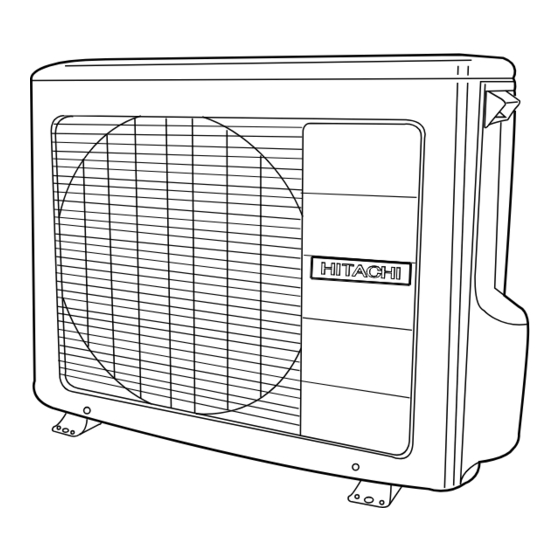
- Page 10 OUTDOOR UNIT DRAIN PIPE Condensed water drain to outside. CONNECTING CORD AIR INLET (BACK, LEFT SIDE) AIR OUTLET MODEL NAME AND DIMENSIONS MODEL WIDTH (mm) HEIGHT (mm) DEPTH (mm) RAK-60PPA 1030 RAC-60WPA – 9 –...
- Page 11 INDOOR UNIT INDICATORS TIMER LAMP This lamp lights when the timer is working. OPERATION LAMP This lamp lights during operation. The OPERATION LAMP fl ashes in the following cases during heating. (1) During preheating For about 2–3 minutes after starting up. (2) During defrosting Defrosting will be performed about once an hour when frost forms on the heat exchanger of the...
- Page 12 Note The recommended temperature range for safety testing should be as below: ● Cooling Heating Minimum Maximum Minimum Maximum Dry bulb °C Indoor Wet bulb °C Dry bulb °C Outdoor Wet bulb °C CIRCUIT BREAKER When you do not use the room air conditioner, set the circuit breaker to “OFF”. MEMO ......................................
- Page 13 THE IDEAL WAYS OF OPERATION Suitable Room Temperature Install curtain or blinds It is possible Warning to reduce Freezing temperature heat entering is bad for health and a the room waste of electric power. through windows. Ventilation Effective Usage Of Timer At night, please use the “OFF or ON timer Caution operation mode”, together with your wake...
- Page 14 FOR USER’S INFORMATION The Air Conditioner And The Heat Source In The Room Caution If the amount of heat in the room is above the cooling capability of the air conditioner (for example: more people entering the room, using heating equipments and etc.), the preset room temperature cannot be achieved.
- Page 15 ATTACHING THE AIR PURIFYING FILTERS CAUTION Cleaning and maintenance must be carried out when fi lter lamp lights. Before cleaning, stop operation and switch off the power supply. Open the front panel ● Pull up the front panel by holding it at both sides with both hands.
- Page 16 MAINTENANCE CAUTION Cleaning and maintenance must be carried out only by qualifi ed service personal. Before cleaning, stop operation and switch off the power supply. PRE-FILTER Clean the Pre-fi lter, as it removes dust inside the room. In case the Pre-fi lter is full of dust, the air fl ow will decrease and the cooling capacity will be reduced.
- Page 17 Washable Front Panel Remove the front panel and wash with clean water. ● Wash it with a soft sponge. After using neutral detergent, wash thoroughly with clean water. When front panel is not removed, wipe it with a soft ● dry cloth.
- Page 18 CAUTION Cleaning and maintenance must be carried out only by qualifi ed service personnel. Before cleaning, stop operation and switch off the power supply. MAINTENANCE AT BEGINNING OF LONG OFF PERIOD Run the unit by setting the operation mode to (COOL), ●...
- Page 19 AFTER SALE SERVICE AND WARRANTY WHEN ASKING FOR SERVICE, CHECK THE FOLLOWING POINTS. CONDITION CHECK THE FOLLOWING POINTS If the remote controller is Do the batteries need replacement? ● not transmitting a signal. Is the polarity of the inserted batteries correct? ●...
- Page 20 PREPARATION BEFORE OPERATION ■ To install the batteries 1. Slide the cover to take it off. 2. Install two dry batteries AAA.LR03 (alkaline). The direction of the batteries should match the marks in the case. 3. Replace the cover at its original position. ■...
- Page 21 PREPARATION BEFORE OPERATION ■ To set calendar and clock 1. Press (RESET) button when fi rst time setting. "Year" blinks. 2. Press (TIME) button to set the current year. 3. Press (CLOCK) button. "Day" and "Month" blink. 4. Press (TIME) button to set the current day and month.
- Page 22 NAMES AND FUNCTIONS OF REMOTE CONTROLLER REMOTE CONTROLLER This controls the operation of the indoor unit. The range of control is about 7 meters. If indoor lighting is ● controlled electronically, the range of control may be shorter. This unit can be fi xed on a wall using the fi xture provided. Before fi xing it, make sure the indoor unit can be controlled from the remote controller.
- Page 23 NAMES AND FUNCTIONS OF REMOTE CONTROLLER MODE selector Button POWERFUL Button Use this button to select the Use this button to set the operating mode. Every time you POWERFUL mode. ( p. 28) press this button, the mode will (AUTO) ➞ change from (HEAT) ➞...
- Page 24 VARIOUS FUNCTIONS ■ Auto Restart Control If there is a power failure, operation will be automatically restarted when the power is resumed with previous operation ● mode and airfl ow direction. (As the operation is not stopped by remote controller.) If you intend not to continue the operation when the power is resumed, switch off the power supply.
- Page 25 HEATING OPERATION Use the device for heating when the outdoor temperature is under 21°C. ● When it is too warm (over 21°C), the heating function may not work in order to protect the device. In order to maintain reliability of the device, please use this device when outdoor temperature is above ●...
- Page 26 DEHUMIDIFYING OPERATION Use the device for dehumidifying when the room temperature is over 16°C. When it is under 15°C, the dehumidifying function will not work. Press the MODE selector button so that the display indicates (DEHUMIDIFY). The fan speed is set at LOW. Press (FAN SPEED) button to select SILENT or LOW fan speed.
- Page 27 COOLING OPERATION Use the device for cooling when the outdoor temperature is -10~ 43°C. If indoors humidity is very high (80%), some dew may form on the air outlet grille of the indoor unit. Press the MODE selector button so that the display indicates (COOL).
- Page 28 FAN OPERATION User can use the device simply as an air circulator. Press the MODE selector so that the display indicates (FAN). Set the desired FAN SPEED with the (FAN SPEED) button (the display indicates the setting). (HIGH) (MED) (LOW) (SILENT) START Press the...
- Page 29 POWERFUL OPERATION By pressing (POWERFUL) button during AUTO, HEATING, DEHUMIDIFYING, COOLING or FAN ● operation, the air conditioner performs at the maximum power. During POWERFUL operation, cooler or warmer air will be blown out from indoor unit for COOLING or ●...
- Page 30 SILENT OPERATION By pressing (SILENT) button during AUTO, HEATING, DEHUMIDIFYING, COOLING or FAN ● operation, the fan speed will change to ultra slow. ■ To start SILENT operation Press (SILENT) button during operation. ● “ ” is displayed on the LCD. Fan speed will be ultra slow. ■...
- Page 31 ECO OPERATION ECO operation is an energy saving function by changing set temperature automatically and by limiting the maximum power consumption value. By pressing the (ECO) button during AUTO, HEATING, ● DEHUMIDIFYING or COOLING operation, the air conditioner performs the "ECO" operation. ■...
- Page 32 LEAVE HOME(LH) OPERATION Prevent the room temperature from falling too much by setting temperature 10°C automatically when no one is at home. This operation is able to operate by "Continuous operation" or "Day timer operation". Please use "Day timer operation" to set the number of days up to 99 days.
- Page 33 CLEAN (ONE TOUCH CLEAN) OPERATION Drying indoor heat exchanger after cooling operation to prevent mildew. ■ To start CLEAN operation Press (CLEAN) button when unit is OFF. ● Total time taken for One Touch Clean operation is 60 minutes. During this operation, HEATING or FAN operation shall operate.
- Page 34 ONCE TIMER (ON/OFF TIMER) OPERATION OFF TIMER The device can be set to turn off at a preset time. 1. Press (OFF-TIMER) button. blink on the display. 2. Set the "turn-off time" with (TIME) button. 3. After setting, direct the remote controller towards the indoor and press (SEND) button.
- Page 35 ECO SLEEP TIMER OPERATION The timer can be set up to a duration of 7 hours. By pressing (SLEEP) button during AUTO, HEATING, DEHUMIDIFYING, COOLING or FAN operation, the unit shifts the room temperature and reduces the fan speed. It results in energy saving. Set the current time fi...
- Page 36 ECO SLEEP TIMER OPERATION ■ To set ECO SLEEP TIMER and ON TIMER The air conditioner will be turned off by ECO SLEEP TIMER and turned on by ON TIMER. 1. Set the ON TIMER. 2. Press (SLEEP) button and set ECO SLEEP TIMER. Example: In this case, air conditioner will turn off in 2 hours (at 1:38) and it will be turned on at 6:00 the next morning.
- Page 37 WEEKLY TIMER OPERATION It is possible to select Mode A or Mode B. For each mode, up to 6 programs can be set per day. In total, a ● maximum of 42 programs can be set for a week for each mode. If calendar and clock are not set, the reservation setting for WEEKLY TIMER cannot be set.
- Page 38 WEEKLY TIMER OPERATION 5. Press (ON-OFF TIMER) button to select ON TIMER or OFF TIMER reservation. 6. Press (TIME) button to set time reservation. 7. Press (TEMP ) button to set temperature reservation. 8. Press (OK) button. The reservations are set. Day, program number, ON reservation, setting temperature will light up.
- Page 39 WEEKLY TIMER OPERATION Step 2: Select Mode A or Mode B and activate or deactivate WEEKLY TIMER. ■ How to select Mode A or Mode B of WEEKLY TIMER setting. 1. Press (WEEKLY) button. blink on the display. (Normally Mode A will blink fi rst). 2.
- Page 40 WEEKLY TIMER OPERATION Step 3: Copy and cancel the reservation schedule. ■ How to copy and paste. Editing the reservation schedule is easy by copying data from one day to another day. 1. Press (WEEKLY) button to select Mode A or Mode B. 2.
- Page 41 WEEKLY TIMER OPERATION Step 3: Copy and cancel the reservation schedule. ■ How to delete WEEKLY TIMER data. [Delete one program number reservation] 1. Press (WEEKLY) button to select Mode A or Mode B. 2. Press (WEEKLY) button for 3 seconds to start editing the reserva- tion schedule.
- Page 42 WEEKLY TIMER OPERATION Step 3: Copy and cancel the reservation schedule. [Delete one day reservation] 1. Press (WEEKLY) button to select Mode A or Mode B. 2. Press (WEEKLY) button for 3 seconds to start editing the reservation schedule. 3. Press (DAY) button to select a day of the week to edit.
- Page 43 INFO FUNCTION By pressing (INFO) button, temperature around remote controller and monthly power consumption will be ● displayed on the remote controller. After changing the batteries, direct the remote controller towards the indoor unit and press (INFO) button. ● Current calendar and clock will be transmitted from indoor unit. In order to receive information from indoor unit, the distance between remote controller and receiver of indoor units is ●...
- Page 44 OPERATION MODE LOCK The remote controller can be set to fi x the HEATING mode (including FAN), COOLING mode (including FAN) and DEHUMIDIFYING mode (including FAN) operations. ■ Method to lock HEATING mode (including FAN) operation. Press (ECO) and (POWERFUL) buttons simultaneously for about 5 seconds when the remote controller is OFF.
-
Page 45: Construction And Dimensional Diagram
CONSTRUCTION AND DIMENSIONAL DIAGRAM MODEL RAK-60PPA – 44 –... - Page 46 CONSTRUCTION AND DIMENSIONAL DIAGRAM MODEL RAC-60WPA – 45 –...
-
Page 47: Main Parts Component
MODEL POWER SOURCE DC: 100 ~ 322V OUTPUT CONNECTION (Control circuit built in) OUTDOOR FAN MOTOR Fan Motor Specifi cations MODEL RAC-60WPA ITEM POWER SOURCE DC: 120 ~ 380V OUTPUT (W) MAX COIL 20°C U-V 35 ± 2.5 V-W 35 ± 2.5 W-U 35 ±... - Page 48 COMPRESSOR MOTOR Compressor Motor Specifi cations MODEL RAC-60WPA COMPRESSOR MODEL JU1015D9 PHASE SINGLE RATED VOLTAGE AC 220 ~ 240 V RATED FREQUENCY 50 Hz POLE NUMBER CONNECTION 20°C 2M = 1.2984 (68°F) RESISTANCE VALUE 75°C 2M = 1.7671 (167°F) CAUTION When the Air Conditioner has been operated for a long time with the capillary tubes clogged or crushed or with too little refrigerant, check the color of the refrigerant oil inside the compressor.
- Page 49 – 48 –...
-
Page 50: Circuit Diagram
CIRCUIT DIAGRAM Remote Control – 49 –... - Page 51 CIRCUIT DIAGRAM MODEL RAK-60PPA – 51 –...
- Page 52 CIRCUIT DIAGRAM MODEL RAC-60WPA – 53 –...
-
Page 53: Printed Wiring Board Location Diagram
PRINTED WIRING BOARD LOCATION DIAGRAM MODEL RAK-60PPA MAIN P.W.B. Marking on P.W.B COMPONENT SIDE SOLDERING SIDE RECEIVING P.W.B. Marking on P.W.B – 55 –... - Page 54 MODEL RAC-60WPA P.W.B. MAIN – 56 –...
- Page 55 – 57 –...
- Page 56 – 58 –...
- Page 57 – 59 –...
- Page 58 – 61 –...
- Page 59 – 63 –...
- Page 60 – 65 –...
- Page 61 – 67 –...
- Page 62 – 69 –...
- Page 63 Temperature Calculated difference compressor rpm 1.66 1965 min –1 –1 2135 min 2.33 2300 min –1 2.66 2465 min –1 2635 min –1 3.33 2800 min –1 3.66 2965 min –1 3135 min –1 4.33 3300 min –1 4.66 3465 min –1 3635 min –1...
- Page 64 – 73 –...
- Page 65 – 75 –...
-
Page 66: Refrigerating Cycle Diagram
REFRIGERATING CYCLE DIAGRAM MODEL RAK-60PPA/RAC-60WPA – 77 –... - Page 67 – 78 –...
-
Page 68: Description Of Main Circuit Operation
DESCRIPTION OF MAIN CIRCUIT OPERATION MODEL RAK-60PPA 1. Reset Circuit – 79 –... - Page 69 R297 – 80 –...
- Page 70 5. Auto Sweep Motor Circuit Fig. 5-1 Auto Sweep Motor Circuit (Horizontal air defl ectors) Fig. 5-1 shows the Auto sweep motor drive circuit; the signals shown in Fig. 5-2 are output from pins ● – of the micro computer. Fig.
- Page 71 6. Room Temperature Thermistor Circuit Fig. 6-1 shows the room temperature The voltage at A depends on the room ● ● thermistor circuit. temperature as shown in Fig. 6-2. 7. Heat exchanger temperature thermistor circuit The circuit detects the indoor heat ●...
- Page 72 – 83 –...
- Page 73 – 84 –...
- Page 74 DESCRIPTION OF MAIN CIRCUIT OPERATION 1. Power Circuit – 85 –...
- Page 75 – 86 –...
- Page 76 – 87 –...
- Page 77 – 88 –...
- Page 78 – 89 –...
- Page 79 – 90 –...
- Page 80 – 91 –...
- Page 81 – 92 –...
-
Page 82: Service Call Q
SERVICE CALL Q & A – 93 –... - Page 83 – 94 –...
- Page 84 – 95 –...
- Page 85 – 96 –...
-
Page 86: Trouble Shooting
TROUBLE SHOOTING – 97 –... - Page 87 – 98 –...
- Page 88 – 99 –...
- Page 89 – 100 –...
- Page 90 – 101 –...
- Page 91 – 102 –...
- Page 92 – 103 –...
- Page 93 – 104 –...
- Page 94 CHECKING INDOOR UNIT ELECTRICAL PARTS MODEL RAC-60WPA 1. Power does not come on (no operation) – 105 –...
- Page 95 – 106 –...
- Page 96 – 107 –...
- Page 97 – 108 –...
- Page 98 – 109 –...
- Page 99 – 110 –...
- Page 100 – 111 –...
- Page 101 – 112 –...
- Page 102 – 113 –...
- Page 103 – 114 –...
- Page 104 – 115 –...
- Page 105 – 116 –...
- Page 106 1. Switch OFF main power supply. 2. Short circuit between JW001 and JW002. 3. Switch ON main power supply – LD301 will blink 1 time. 4. (Within 3 minutes) Press Test/Service Switch for 1 second or more. 5. Self-diagnosis result will be shown – LD303 will ON (LIT) and LD301 will be blinking. Then refer to diagnosis table 2.
- Page 107 – 118 –...
- Page 108 – 119 –...
- Page 109 – 120 –...
- Page 110 CHECKING THE REMOTE CONTROLLER – 121 –...
- Page 111 – 122 –...
-
Page 112: Parts List And Diagram
PARTS LIST AND DIAGRAM INDOOR UNIT MODEL : RAK-60PPA – 123 –... - Page 113 MODEL RAK-60PPA PART NO. T ’ PARTS NAME RAK-60PPA PMRAS-70YHA CABINET PMRAS-40CNH2 MOUNTING PLATE PMRAS-70YHA FAN MOTOR PMRAS-70YHA TANGENTIAL FAN PMRAS-25CNH2 P-BEARING ASSY PMRAS-51CHA1 FAN MOTOR BASE PMRAK-60PPA CYCLE ASSY PMRAS-51CHA1 FAN COVER PMRAS-18CP5 PIPE SUPPORT PMRAS-70YHA DRAIN PAN ASSY PMRAS-18CP6 AUTO SWEEP MOTOR PMRAS-70YHA...
- Page 114 PARTS LIST AND DIAGRAM OUTDOOR UNIT MODEL : RAC-60WPA – 125 –...
- Page 115 MODEL RAC-60WPA PART N0. Q’TY / UNIT PARTS NAME RAC-60WPA PMRAC-60YHA2 SV-COVER PMRAC-60YH7 COMPRESSOR KPNT1 PUSH NUT RAC-2226HV COMPRESSOR RUBBER PMRAC-50NH4 CONDENSER PMRAC-X24CAT REVERSING VALVE PMRAC-25NPA ELECTRICAL EXPANSION COIL PMRAC-50NH4 VALVE (2S) PMRAC-60YHA3 VALVE (4S) PMRAC-40CNH2 THERMISTOR (OH) PMRAC-25NH4 OVERHEAT THERMISTOR SUPPORT...
- Page 116 HITACHI RAK-60PPA / RAC-60WPA PM NO. 0540E Printed in Malaysia...
Need help?
Do you have a question about the RAC-60WPA and is the answer not in the manual?
Questions and answers