
Summary of Contents for Parktron CPS2000
- Page 1 CPS2000 Chipcoin Parking System Entry/Exit Terminal - CENT209/CEXT209 Installation Manual Version 4.0 Issue Date: 2014.01...
-
Page 2: Table Of Contents
2.2. Connect barrier gate to terminal: ................ 14 2.2.1. Terminal I/O control board wiring contact points reference: ....14 2.2.2. Barrier gate wiring diagram (for Parktron barrier AGT210): ...... 16 2.2.3. For other types of barrier:................ 18 2.3. DC power outputs of terminal device & signal inputs: ......... 21 2.3.1. - Page 3 4.4. Tips to use Unix editor tool “vi”: ................35 Revision History: Version Released Date Revision Notes 2010.02 First edition release 2010.09 Linux system version 1.0 2011.08 Add Section 3.2.5. 2012.11 Content update 2012.12 Change document format 2014.01 Change document format © 2014 - 2024 Parktron Technology Ltd.
-
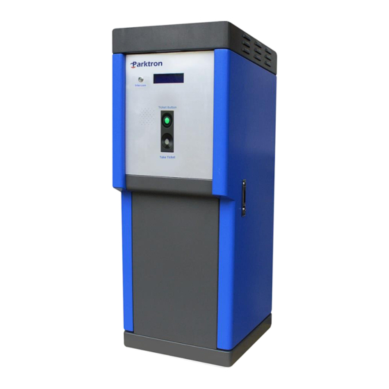
Page 4: Cabinet Installation (Entry/Exit Terminal)
Note:Two(2) terminal keys are hanged on to the lock node inside of cabinet door. Entry Terminal Exit Terminal © 2014 - 2024 Parktron Technology Ltd. -
Page 5: Foundation Island Preparation
1.2.1. Suggested dimensions: A cement foundation island for installing terminal and barrier is recommended with the suggested dimensions as: 20cm(H) x 460cm(L) x 80cm (W) to ensure the safety of equipment and service personnel. © 2014 - 2024 Parktron Technology Ltd. -
Page 6: Power, Network Cable, Control Signal & Intercom Wires
Refer to figure below for embedding dimension reference: Or drill and install expansion type of bolts (M16 stainless steel) as below picture: © 2014 - 2024 Parktron Technology Ltd. - Page 7 Terminal - Anchor bolts location reference: Two(2) metal fasten bars to secure terminal on to anchor bolts. Barrier (Only for AGT210 barrier purchased from Parktron) - Anchor bolts location reference: © 2014 - 2024 Parktron Technology Ltd.
-
Page 8: Detection Loop Wire Installation
Loop lead to terminal of LOOP1 and LOOP2 should not over cross each other. The loop wire pair (from loop lead-in to terminal) need to be twisted (about 20 times per meter). © 2014 - 2024 Parktron Technology Ltd. -
Page 9: Ground Slot Cutting For Loop Wire Installation
Suggested length of X is drive way width minus 100cm (50cm from each side of the drive way edge). Each corner would have a 10cm x 10cm chamfer. Loop wire lead in position “L” normally on short length side. © 2014 - 2024 Parktron Technology Ltd. - Page 10 2.5cm + Number of loop turns x 0.2cm Suggested cutting tool: A 4” or above wet (water proof) circular saw with diamond blade. Note:Pour water to prevent heavy dust while cutting. © 2014 - 2024 Parktron Technology Ltd.
-
Page 11: Loop Wire Installation Instruction
7. Scratch off extra sealant to maintain a flat surface of the drive way. Do not make the sealant top higher than the drive way surface to avoid wire loops get damaged by passing cars. © 2014 - 2024 Parktron Technology Ltd. -
Page 12: Cable & Wire Connection
2.1. Connect loop wires to loop detectors: 2.1.1. Where are loop detectors? Loop detectors are option items to be purchased, and if purchased from Parktron, they will be pre-installed inside terminal cabinet (refer to image below). If not purchased from Parktron, please verify your loop detectors are functional compatible with Parktron system. -
Page 13: Loop Detector Configuration & Testing
If blinking very slowly, loop wiring does not have enough turns. Add extra loop turns until DETECT LED light is not blinking. If blinking very rapidly, loop wiring has too many turns. Remove loop turns until DETECT LED light is not blinking. © 2014 - 2024 Parktron Technology Ltd. -
Page 14: Connect Barrier Gate To Terminal
JP2 – Adjust jumper according to barrier gate open/close control signal common point: If common point is 0V (GND), make jumper middle pin short with BR_GND. If common point has +12~24V (V+), make jumper middle pin short with BR_V+. © 2014 - 2024 Parktron Technology Ltd. - Page 15 Barrier control circuit: © 2014 - 2024 Parktron Technology Ltd.
-
Page 16: Barrier Gate Wiring Diagram (For Parktron Barrier Agt210)
2.2.2. Barrier gate wiring diagram (for Parktron barrier AGT210): For system with 110VAC power source: © 2014 - 2024 Parktron Technology Ltd. - Page 17 For system with 220VAC power source: © 2014 - 2024 Parktron Technology Ltd.
-
Page 18: For Other Types Of Barrier
Barrier open/close signal common = +12V~+24V (V+). Output signal type of barrier arm open position: Active high. When barrier arm reach highest (open) position: Up Position output signal 0V -> +5V~+24V. © 2014 - 2024 Parktron Technology Ltd. - Page 19 Type 4: Barrier open/close signal common = GND (0V). Output signal type of barrier arm close position: Relay output N.C. When barrier arm reach lowest (close) position: N.C. -> Open. © 2014 - 2024 Parktron Technology Ltd.
- Page 20 Barrier open/close signal common = GND (0V). Output signal type of barrier arm close position: Active low. When barrier arm reach lowest (close) position: Down Position output signal +5V~+24V -> 0V. © 2014 - 2024 Parktron Technology Ltd.
-
Page 21: Dc Power Outputs Of Terminal Device & Signal Inputs
Spare input Spare input Spare input DB25-3/25 Accept barrier gate open signal from Exit-POS (pay-at-exit & B2 Cashier Station) or other access control system (building access control, license plate recognition, remote access system). © 2014 - 2024 Parktron Technology Ltd. -
Page 22: Wiring Contacts For Software Programmable Functions
Normally utilized by parking space counting system, exit warning light …etc. O-LOOP2 Output signal from loop detector 2. O-LOOP1 Output signal from loop detector 1. O-2-A7 Spare Output O-2-A6 Spare Output © 2014 - 2024 Parktron Technology Ltd. -
Page 23: Intercom Wiring Reference
Intercom sub unit is installed on the face plate of a terminal. It is compliant to AIPHONE LE room subs. J1(I/P): Connect to J2 (TD SW): Connect to Master unit (back intercom push button on to central control terminal faceplate. room). © 2014 - 2024 Parktron Technology Ltd. -
Page 24: Master Unit Requirement
2.4.3. Master unit requirement: Intercom master unit is optional to be purchased by projects. Parktron provides selection of the followings: AIPHONE LEF-3 / LEF-5 / LEF-10 / LEF-10S, or any AIPHONE compatible intercom device should work at own purchase. 2.5. Network cable connection: 2.5.1. -
Page 25: Input Power Cable Connection
2.6. Input power cable connection: 2.6.1. Terminal input power requirement: Depends on local requirement, Parktron supply two(2) voltages option: 110~120VAC 6A. 220~240VAC 3A. 2.6.2. Input power connection location: Connect input power wires to the circuit breaker input side. -
Page 26: Power On & Configuration
3. Power on & configuration: Note:Normally, terminal configuration parameters and IP address have been pre-configured before shipping out of Parktron factory. The terminal should be ready to run after properly connected to power and system network. Only refer and apply the following sections when installation requires IP address or configuration parameters change. -
Page 27: Configure Terminal Ip Address
3.3. Configure terminal IP address: Note:Skip this section if IP address does not need to be changed. With the command “cd LocalSeting/” to change current working directory to “LocalSeting” directory. © 2014 - 2024 Parktron Technology Ltd. -
Page 28: Specify Terminal Program For Entry Or Exit
Under LocalSeting file directory, the filename “location.in” makes the terminal program to run in entry mode. When rename to “location.out”, it makes the terminal program to run in exit mode. Use command like “mv location.in location.out” to rename “location.in” to “location.out”. © 2014 - 2024 Parktron Technology Ltd. -
Page 29: Time Synchronization
Note:The Parking.ini lists all the configuration data for every entry and exit terminals on the system. In case of losing a Parking.ini in one terminal, you can copy it from other terminal and use it. © 2014 - 2024 Parktron Technology Ltd. - Page 30 program integrated. Set 0 if LPR system is not integrated. PlateTimeout: Timeout setting for waiting LPR program reply. LED888Type: Total space LED display type connected to the Terminal, currently only © 2014 - 2024 Parktron Technology Ltd.
- Page 31 2: Dual Mifare card dispenser (upgrade option). MifareDispenser: COM port number to connect Chipcoin dispenser (refer to above image). BinsSize: Capacity of problem card (ticket) recycle bin. PreTicket: Pre-issue card (ticket) to increase dispensing speed. © 2014 - 2024 Parktron Technology Ltd.
- Page 32 ParkingID: Unique ID for individual parking facility within a country region. This is pre-assigned by Parktron, and please do not change it unless instructed. ServerIP: The server IP address of the parking system. Confirm the IP address is the ...
-
Page 33: Edit Machine Sn
Use ftp client software “FileZilla” to connect to terminal (must login with the account “parktron” and password “pt12885568”), and upload “main” and other program files (if any) to the directory “/Data/ApUpload” on terminal file system. Note:FileZilla free download URL: http://filezilla-project.org/download.php?type=client... -
Page 34: How To" Collection
4. “How to” collection: 4.1. How to copy log files: In cases the terminal has problem need to be diagnostic by Parktron engineers, please follow the steps to obtain log files for diagnose: Use ftp client software “FileZilla” (refer to above section for download information) ... -
Page 35: How To Set Exact Terminal Date & Time
To start edition, press “i” to insert words; “d” to delete words; and “Esc” to exit edition mode. After exit edition mode, either type “:q!” to exit file without saving the change, or type “:wq” to save the change and exit. © 2014 - 2024 Parktron Technology Ltd.
Need help?
Do you have a question about the CPS2000 and is the answer not in the manual?
Questions and answers