Table of Contents
Advertisement
Quick Links
Advertisement
Table of Contents

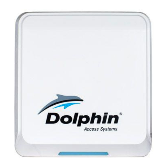
Summary of Contents for Dolphin DOLCWIUHF-910
- Page 1 UHF LONG RANGE READER (DOLCWIUHF-910) INSTALLATION MANUAL...
-
Page 2: Table Of Contents
User Manual of DOLCWIUHFP Content 1 Introduction............................ 2 1.1 Functions............................2 1.1.1 Working principle........................2 1.1.2 Working Mode ........................2 1.1.3 Parameters ..........................3 1.2 System Description......................... 3 1.2.1 Components..........................3 1.2.2 Host............................4 1.2.3 Interface..........................4 1.2.4 LED Indicator ........................... 4 1.2.5 Buzzer............................ -
Page 3: Introduction
User Manual of DOLCWIUHFP This device complies with parts 15 of the FCC Rules. Operation is subject to the following two conditions: (1) This device may not cause harmful interference, and (2) This device must accept any interference received, including interference that may cause undesired operation. Changes or modification not expressly approved by the party responsible for compliance could void the user’s authority to operate the equipment. -
Page 4: Parameters
User Manual of DOLCWIUHFP 1.1.3 Parameters The parameters of Transmitter Solutions DOLCWIUHFP Table 1.1.3-1 Table 1.1.3-1 Parameter Value Operating Frequency 902 928 MHz FHSS Transmitter Power 0.5 to 2W (programmed by software) Supply Voltage 10~25 VDC +5%/-1%, Ripple: maximum 50 mV Communication Rates 9600 bps Power Consumption... -
Page 5: Host
User Manual of DOLCWIUHFP 1.2.2 Host Over view Side view Back view 1.2.3 Interface Transmitter Solutions DOLCWIUHFP can be able to provide 5 group interface, for details please refer Table 1.2.3-1 Table 1.2.3-1 Definition of the Interface Interface Type Definition Color +12 V Power Pins... -
Page 6: Buzzer
User Manual of DOLCWIUHFP Red LED lighting means the DOLCWIUHFP is power on, while Blue LED lighting means the DOLCWIUHFP captures the data of the tag, 1.2.5 Buzzer When DOLCWIUHFP captures the data of the tag, the buzzer will beep. 1.2.6 Label Label Type Definition... -
Page 7: Reader Installation
User Manual of DOLCWIUHFP 2 Reader Installation 2.1 Installation Overview The Reader has been designed with easy installation in mind. The Figure 2.1-1 provides you with any details that you will need to know. Figure 2.1-1 Installation 2.2 M 2.2 Installation Summary There are two ways for installing Transmitter Solutions DOLCWIUHFP by install position. -
Page 8: Side Installation
User Manual of DOLCWIUHFP When the site meets following conditions, we suggest choosing the Overhead Installation way, otherwise choosing the Side Installation way: There are many types of car, especially with both large vehicle and small car; The position of the tag is different from different type of vehicles; The drive position is available for both left and right side 2.3 Side Installation 2.3.1 Overview... -
Page 9: Notice
User Manual of DOLCWIUHFP Table 2.3.2-1 Description Position A Position B Install Height Over 2.2 m (see the Left View of Position B in Figure 2.3.1-1) Pole Position (H) Over 0.25 m horizontal far from the edge of the lane (See Over View of Side Installation in Figure 2.3.1-1 Pole Position (V) -
Page 10: Instruction
User Manual of DOLCWIUHFP Figure2.4.1-1 2.4.2 Instruction The instruction mentioned in the Table 2.4.2-1 is based on the example showed on the Figure 2.4.1-1, if not suitable for your site, you can contact with Transmitter Solutions for assistance. Tabel 2.4.2-1 Description Overhead Installation Install Height... -
Page 11: Tag Installation
User Manual of DOLCWIUHFP 3. The data wire should be with shielding layer and should be connected with the GND to avoid any interference. 4. Adjust the reader range to make sure the tag can be detected when the vehicle with the tag is approaching ticket box and within one lane area only, so that there is only one vehicle and one tag in the operation area to avoid any wrong operation. - Page 12 User Manual of DOLCWIUHFP 3.2.1.2 Installation for Tags For the vehicles without metalized windshield, you can choose one of six places showed on figure 3.2.1-1 to install For the vehicles with the pre-configured metalized windshield, it should have a reserved area with 120(L) * 70(W) mm that not metalized for RFID tags according to the European Standard, usually in the place B, so you can install the tag on this reserved area.
- Page 13 User Manual of DOLCWIUHFP 3.2.2 Sticker The install way is same as card holder, for details refer to 3.2.1.2. Please note that the tag need to be used by stick on the surface of the window or headlights and cannot able to reuse if rip off.
-
Page 14: Appendix 1 How To Check The Performance Simply
User Manual of DOLCWIUHFP Appendix 1 How to check the performance simply? Purpose: When a malfunction occurs during the using, the follow steps will help you to check the performance of the reader simply. 1. Test Sites: Open area without any barrier or block. 2.
Need help?
Do you have a question about the DOLCWIUHF-910 and is the answer not in the manual?
Questions and answers