
Related Manuals for Unical KUTter R 28

Summary of Contents for Unical KUTter R 28
- Page 1 Библиотека СОК R 28 - B 28 ISTRUZIONI PER L’INSTALLATORE E IL MANUTENTORE INSTALLATION AND SERVICING MANUAL...
- Page 2 http://www.unicalag.it/prodotti/domestico-50/condensazione-gas/1335/kutter-b...
-
Page 3: Table Of Contents
Attenzione il presente manuale contiene istruzioni ad uso esclusivo dell’installatore e/o del manutentore professionalmente qualificato, in conformità alle leggi vigenti. L’utente NON è abilitato a intervenire sulla caldaia. Nel caso di danni a persone, animali o cose derivanti dalla mancata osservanza delle istruzioni conte- nute nei manuali forniti a corredo con la caldaia, il costruttore non può... -
Page 4: Informazioni Generali
INFORMAZIONI GENERALI 1.1 - AVVERTENZE GENERALI parecchio, disattivarlo, astenendosi da qualsiasi Il libretto d’istruzioni costituisce parte integrante ed tentativo di riparazione o di intervento diretto. Rivol- essenziale del prodotto e dovrà essere conservato gersi esclusivamente a personale abilitato ai sensi dall’utente. -
Page 5: Simbologia Utilizzata Nel Manuale
1.2 - SIMBOLOGIA UTILIZZATA NEL MANUALE Nella lettura di questo manuale, particolare attenzione deve essere posta alle parti contrassegnate dai simboli rappresentati: NOTA! PERICOLO! NOTA! ATTENZIONE! Per maggiori informazioni Grave pericolo Possibile situazione Suggerimenti consultare Info Tecniche: per l’incolumità per l’utenza pericolosa per il prodotto e la vita all’indirizzo indicato... -
Page 6: Avvertenze Per La Sicurezza
1.5 - AVVERTENZE PER LA SICUREZZA ATTENZIONE! L’apparecchio non puo’ essere utilizzato da bambini. L’apparecchio puo’ essere utilizzato da persone adulte e solo dopo avere letto attentamente il manuale di istruzione d’uso per l’utente. I bambini devono essere sorvegliati affinchè non giochino o manomettano l’ap- parecchio. -
Page 7: Targhetta Dati Tecnici
1.6 - TARGHETTA DEI DATI TECNICI Marcatura CE LEGENDA: La marcatura CE documenta che le caldaie soddi- 1 = Ente di sorveglianza CE sfano: 2 = Tipo di caldaia - I requisiti essenziali della direttiva relativa agli 3 = Modello caldaia apparecchi a gas (direttiva 2009/142/EEC) 5 = (S.N°) Matricola - I requisiti essenziali della direttiva relativa alla... -
Page 8: Trattamento Dell'acqua
1.7 - TRATTAMENTO DELL’ACQUA ATTENZIONE! Il trattamento delle acque di alimen- QUALSIASI DANNO PROVOCATO tazione consente di prevenire gli ALLA CALDAIA, DOVUTO ALLA inconvenienti e mantenere funzio- FORMAZIONE DI INCROSTAZIONI O nalità ed efficienza del generatore DA ACQUE CORROSIVE, NON SARà nel tempo. -
Page 10: Caratteristiche Tecnichee Dimensioni
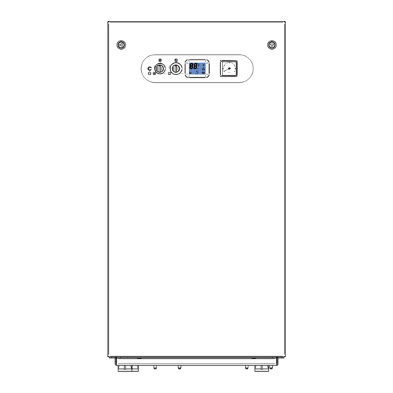
CARATTERISTICHE TECNICHE E DIMENSIONI NOTA! Per maggiori informazioni 2.1 - CARATTERISTICHE TECNICHE consultare Info Tecniche dal sito 2.2 - VISTA CON L’INDICAZIONE DEI COMPONENTI PRINCIPALI E DIMENSIONI KUTter R 28... - Page 11 KUTter R 28 Vista da dietro Vista dall’alto...
- Page 12 KUTter B 28...
- Page 13 KUTter B 28 Vista da dietro Vista dall’alto...
- Page 14 LEgENDA Circolatore modulante im- N° C.E. S.E. Descrizione pianto Valvola gas Compensatore Idraulico di Elettrodo di accensione/rile- bilanciamento vazione /RIL Anodo Bruciatore Uscita acqua calda Vaso di espansione sanitaria ½ riscaldamento Ingresso gas Termostato di sicurezza ¾ Sensore di temperatura ri- Ingresso acqua fredda scaldamento ½...
- Page 15 2.3 - DIAGRAMMA PORTATA/PRESSIONE DISPONIBILE PER L’INSTALLAZIONE CIRCOLATORE IMPIANTO- KUTter R 2.3.1 - DIAGRAMMA PORTATA/PRESSIONE DISPONIBILE PER L’INSTALLAZIONE Portata (l/h) By-pass chiuso By-pass aperto...
-
Page 16: Circolatore Mandata Impianto
CIRCOLATORE MANDATA IMPIANTO - SOLO PER KUTter B A valle del compensatore idraulico, le caldaie sono fornite di un circolatore di rilancio all’impianto di tipo elettronico a basso consumo, le cui caratteristiche di portata / prevalenza sono riportate nei grafici indicati a lato. - Page 17 2.3.1 - DIAGRAMMA PORTATA/PRESSIONE DISPONIBILE PER L’INSTALLAZIONE Portata (l/h) Portata (l/h)
- Page 18 2.3.2 - PRODUZIONE ACQUA CALDA SANITARIA KUTTER B 28 47 °C 15 °C 12 l/min. Tempo (sec) 2.4 - DATI DI FUNZIONAMENTO SECONDO UNI 10348 Per i dati di regolazione: UgELLI - PRESSIONI - DIAFRAMMI - PORTATE - CON- SUMI, fare riferimento al paragrafo ADATTAMENTO ALL’UTILIZZO DI ALTRI GAS. KUTTER R 28 B 28...
-
Page 19: Dati Secondo Direttiva Erp
2.4.1 - DATI SECONDO DIRETTIVA ErP KUTTER R 28 B 28 Elemento Simbolo Unità Valore Valore Potenza utile nominale Pnominale 26,9 26,9 Efficienza energetica stagionale del riscaldamento ƞ d’ambiente Classe di efficienza stagionale per riscaldamento Per le caldaie per il riscaldamento d’ambiente e le caldaie miste: potenza termica utile Potenza termica utile in regime di alta temperatura 15,76 15,76... -
Page 20: Istruzioni Per L'installatore
ISTRUZIONI PER L’INSTALLAZIONE 3.1 - AVVERTENZE GENERALI trollo può essere montato il raccordo tra caldaia e camino/canna fumaria; ATTENZIONE! Questa caldaia deve essere desti- ATTENZIONE! nata solo all’uso per il quale è stata Se nel locale di installazione espressamente prevista. Ogni altro sono presenti polveri e/o vapori uso è... -
Page 21: Imballo
3.4 - IMBALLO La caldaia viene fornita completamente assemblata Nell’imballo, oltre all’apparecchio, sono contenute: in una robusta scatola di cartone. A BUSTA DOCUMENTAZIONE Dopo aver rimosso l’apparecchio dall’im- - Libretto istruzioni d’uso per l’utente ballo, assicurarsi che la fornitura sia - Libretto istruzioni per l’installatore e il completa e non danneggiata. -
Page 22: Posizionamento Della Caldaia
3.5 - POSIZIONAMENTO DELLA CALDAIA Nella scelta del luogo di installazione della caldaia Quote di rispetto attenersi alle seguenti indicazioni di sicurezza: - Collocare la caldaia in locali protetti dal gelo. - Evitare l’installazione in locali con atmosfera cor- rosiva o molto polverosa. - Tenere in considerazione il peso dell’apparecchio con il contenuto d’acqua - Evitare collocazione su elementi che facilitano la... - Page 23 KUTter R Attenzione: Scond = Scarico condensa Verificare il drenaggio naturale o forzato in base all’altezza delle prese di scarico disponibili (Par. 3.7)
-
Page 24: Allacciamento Condotto Scarico Fumi
3.6 - ALLACCIAMENTO CONDOTTO SCARICO FUMI (per Caldaie a tiraggio forzato) Per l’allacciamento del condotto scarico fumi sono SEMPRE anche il condotto fumi. da rispettare le normative locali e nazionali La caldaia è omologata per le configurazioni di sca- Nel caso di sostituzione di caldaie, sostituire rico sottoriportate: C13x C43x... - Page 25 C63x B23P Caldaia destinata ad essere collegata ad un siste- ma di adduzione di aria comburente ed evacua- zione dei prodotti della combustione approvato e venduto separatamente. ATTENZIONE: La canna fumaria / camino deve esse- re conforme alle norme vigenti. C83x LUNgHEZZA TOTALE ( LScarico) SDOPPIATO Ø80...
- Page 26 INFORMAZIONI GENERALI SUL SISTEMA DI SCARICO FUMI Attenzione: Per configurazioni di scarico - COASSIALI Ø 60/100 montare il tappo di chiusura sul foro A aspirazione e utilizzare il foro S - SDOPPIATI Ø 80 utilizzare i fori A Aspirazione - S Scarico KUTter B KUTter R Tappo di ispezione corpo in alluminio per manutenzione.
-
Page 27: Allacciamenti
3.7 - ALLACCIAMENTO ANODO (solo modello B) 3/4’’ Pericolo! RUBINETTO DI CARICO L’allacciamento del gas deve essere ese- RUBINETTO entrata acqua fredda guito solo a cura di un installatore abilitato (solo modello B) che dovrà rispettare ed applicare quanto Scond SCARICO CONDENSA previsto dalle leggi vigenti in materia e dalle locali prescrizioni della società... - Page 28 KUTter R La pressione nella rete di alimen- tazione (acquedotto) deve essere compresa tra 1 e 3 bar (nel caso di pressioni superiori è necessario installare un riduttore di pressione).
- Page 29 Scarico condensa La caldaia, durante il processo di combustione, pro- Il collegamento fra apparecchio e l’im- duce condensa che, attraverso il tubo “A”, fluisce pianto smaltimento reflui domestici deve nel sifone. essere realizzato nel rispetto delle spe- La condensa che si forma all’interno della caldaia cifiche norme di riferimento.
-
Page 30: Riempimento Dell'impianto
3.8 - RIEMPIMENTO DELL’IMPIANTO Attenzione! Non miscelare l’acqua del riscalda- mento con sostanze antigelo o anti- corrosione in errate concentrazioni! Può danneggiare le guarnizioni e pro- vocare l’insorgere di rumori durante il funzionamento. Il costruttore declina ogni responsabi- lità nel caso danni procurati a persone, animali o cose subentranti in seguito a mancata osservanza di quanto sopra esposto. -
Page 31: Allacciamenti Elettrici
3.9 - ALLACCIAMENTI ELETTRICI Pericolo! L’installazione elettrica deve essere eseguita solo a cura di un tecnico abilitato. Prima di eseguire i collegamenti o qualsiasi operazione sulle parti elet- triche, disinserire sempre l’alimen- tazione elettrica e assicurarsi che non possa essere accidentalmente reinserita. - Page 32 Collegamento sonda Collegamento termostato Collegamento termostato esterna (*) ambiente modulante ambiente ON/OFF (*) RT/OT (*) - Rimuovere il ponticello e col- - Collegare il cavo del termostato - Predisposto sulla morsettiera, legare i cavi del termostato modulante tra i morsetti TA1/OT morsetti SE dopo aver rimosso il ponticello ambiente tra i morsetti TA 2.
-
Page 33: Prima Accensione
3.10 - PRIMA ACCENSIONE La prima accensione deve essere effet- in seguito a mancata osservanza di quanto sopra tuata da personale professionalmente esposto. qualificato. Il costruttore declina ogni responsabilità nel caso danni procurati Prima della messa in funzione della caldaia è op- a persone, animali o cose, subentranti portuno verificare quanto segue: l’installazione risponde alle specifiche norme e prescrizioni vigenti sia per quanto riguarda la... -
Page 34: Misura In Opera Del Rendimento Di Combustione
3.11 - MISURA IN OPERA DEL RENDIMENTO DI COMBUSTIONE 3.11.1- ATTIVAZIONE DELLA FUNZIONE DI TARATURA ATTENZIONE! L’utente NON è autorizzato all’atti- Funzione riservata esclusivamente ai vazione della funzione di seguito Centri di Assistenza Autorizzati. descritta. MINIMA POTENZA ATTIVAZIONE girando la manopola (B) in posizione , la cal- Premendo il pulsante (D) per 3 secondi, si attiva daia funzionerà... -
Page 35: Regolazione Del Bruciatore
3.12 - REGOLAZIONE DEL BRUCIATORE Attenzione, durante queste operazioni - Rimuovere il tappo ed inserire la sonda di analisi non effettuare prelievi in sanitario. della CO2 nella presa fumi del terminale aspira- zione/scarico, vedi cap. 3.11.2. Tutte le caldaie escono di fabbrica già ta- Tutte le istruzioni di seguito riportate sono rate e collaudate, nel caso sia necessario ad uso esclusivo del personale addetto... - Page 36 2,96 m³/h Propano (g31) 5,3-27 5,6-28 1500 6100 8/10 10,5 10,5 0,34 kg/h 2,17 kg/h i dati riportati sono riferiti al funzionamento in riscaldamento KUTTER R 28 Diaframma Potenza Tipo di Potenza Portata Press. Velocità Livelli CO Consumi Consumi collettore avviam.
-
Page 37: Adattamento Della Potenza All'impianto Do Riscaldamento
3.12.1 - ADATTAMENTO DELLA POTENZA ALL’IMPIANTO DI RISCALDAMENTO ATTENZIONE! L’utente NON è autorizzato all’attivazione della Funzione riservata esclusivamente ai funzione di seguito descritta. Centri di Assistenza Autorizzati. Agire sul parametro HP (par. 4.2 parametri modi- E’ possibile regolare la portata termica massima in riscaldamento, diminuendo il valore di Potenza ficabili da pannello comandi) per ottenere il valore percentuale del bruciatore. -
Page 38: Istruzioni Per L'ispezionee Manutenzione
ISPEZIONI E MANUTENZIONE Ispezioni e manutenzioni effettuate a Ispezioni e Manutenzioni non eseguite regola d’arte ed ad intervalli regolari, non- possono causare danni materiali e per- ché l’utilizzo esclusivo di pezzi di ricambio sonali originali sono di primaria importanza per un funzionamento esente da anomalie ed una garanzia di lunga durata della caldaia. - Page 39 OPERAZIONI DI VERIFICA ANNUALE ORDINARIA COMPONENTE: VERIFICARE: METODO DI CONTROLLO/IN- TERVENTO: L’anodo è in buono stato di con- Svuotare il bollitore ed estrarre (Anodo in magnesio) servazione? l’anodo An (chiave 28 mm), - KUTter B - verificarne l’integrità e l’efficenza, se necessario sostituirlo.
-
Page 40: Parametri Modificabili Da Pannello Comandi
4.2 - PARAMETRI MODIFICABILI DA PANNELLO COMANDI ATTENZIONE! Funzione riservata esclusivamente ai Centri di Assistenza Autorizzati. Alcuni parametri di servizio possono essere modifcati dal pannello comandi: ATTIVAZIONE PRERISCALDO VALORI STANDARD Premendo il pulsante (D) per 10 secondi, si attiva la funzione quando la chiave compare sul display in modo lampeggiante SELEZIONE Ruotare la manopola RISCALDAMENTO ‘’B’’... -
Page 41: Adattamento All'utilizzo Di Altri Gas
DISATTIVAZIONE - Accedere alla scheda di modulazione contenuta Per uscire dall’elenco nel quadro elettrico e posizionare il jumper nella parametri attendere 20” o ruotare rapidamente la posizione corrispondente al nuovo tipo di gas manopola sanitaria ‘‘C’’. indicata in figura; 4.3 - ADATTAMENTO ALL’UTILIZZO DI ALTRI GAS Le caldaie sono prodotte per il tipo di gas specifica- tamente richiesto in fase di ordinazione. -
Page 42: Note Importanti
4.4 - NOTE IMPORTANTI NOTA 4.4.1 - FUNZIONE ANTILEGIONELLA Il pressostato di sicurezza contro la man- (KUTter B / KUTter R + BOLLITORE). canza d’acqua non dà il consenso elettrico Si attiva ogni 7 gg (168 h) se la temperatura del per la partenza del bruciatore quando la bollitore è... -
Page 43: Schema Elettrico
4.5 - SCHEMA ELETTRICO Schema di collegamento pratico VIOLA LEGENDA Sensore riscaldamento ritorno A1..A9 Connettori servizi Sonda sanitario (solo B) Controllo pompa modulante Termostato limite Pressostato sicurezza mancanza acqua Termostato limite collettore fumi E. ACC./RIL Elettrodo accensione/rilevazione Valvola gas Motore valvola deviatrice (solo B) Ventilatore modulante Pompa di caldaia Morsetti di collegamento Sonda esterna... -
Page 44: Codici Di Errore
4.6 - CODICI DI ERRORE ll simbolo lampeggia sul video display quando la caldaia rileva una anomalia. service 1) In caso di anomalia che non provoca il fermo della caldaia, per vi- sualizzare il codice di errore è necessario premere il tasto di sblocco; nel caso la caldaia sia in stand-by il codice di errore compare in modo fisso sul display . - Page 45 VELOCITA’ FUORI Verificare il funzionamento del CONTROLLO ventilatore (18) e le connes- Alterazione della velocità ven- sioni tilatore la velocità non viene raggiunta. VELOCITA’ FUORI Verificare il funzionamento del CONTROLLO ventilatore (18) e le connes- Alterazione della velocità ven- sioni tilatore la velocità...
- Page 46 PARAMETRI DI FABBRICA Premere il tasto di sblocco se Alterazione dei parametri di l’anomalia non scompare, so- fabbrica a causa di eventuali stituire la scheda interferenze elettromagnetiche BLOCCO Verificare l’alimentazione gas Mancanza gas o mancata ac- oppure il buon funzionamento censione bruciatore elettrodo di accensione/rileva- zione (4).
- Page 48 http://www.unicalag.it/prodotti/domestico-50/condensazione-gas/1335/kutter-b...
- Page 49 Attention: this manual contains instructions for the exclusive use of the professionally qualified installer and/or maintenance technician in compliance with current legislation. The user is NOT qualified to intervene on the boiler. The manufacturer will not be held liable in case of damage to persons, animals or objects resulting from failure to comply with the instructions contained in the manuals supplied with the boiler.
-
Page 50: General Information
Any product repairs must be performed solely by The instruction booklet is an integral and essential personnel authorised by Unical, using original spare part of the product and must be kept by the user. parts only. Failure to comply with the above can... -
Page 51: Symbols Used In The Manual
Any other use must be considered improper. UNICAL AG s.p.A. will not be held liable for any damage resulting from improper use. Use according to the intended purposes also includes strict compliance with the in- structions in this manual. -
Page 52: Safety Warnings
1.5 - sAFETY wARNINGs ATTENTION! The boiler cannot be used by children. The boiler can be used by adults and only after having carefully read the user’s ma- nual. Children should be supervised to ensure that they do not play or tamper with the device. -
Page 53: Technical Data Plate
1.6 - Technical daTa plaTe KEY: ce marking 1 = CE monitoring body The CE marking certifies that the boilers meet: - The essential requirements of the gas appliance 2 = Type of boiler directive (directive 2009/142/EEC) 3 = Boiler model - The essential requirements of the electromagnetic 4 = Number of stars (directive 92/42 EEC) compatibility directive (2004/108/EC) - Page 54 1.6 - TEcHNIcAL DATA PLATE KEY: cE marking 1 = CE monitoring body The CE marking certifies that the boilers meet: - The essential requirements of the gas appliance 2 = Type of boiler directive (directive 2009/142/EEC) 3 = Boiler model - The essential requirements of the electromagnetic 4 = Number of stars (directive 92/42 EEC) compatibility directive (2004/108/EEC)
-
Page 55: Water Treatment
1.7 - WATEr TrEATMENT ATTENTION! The treatment of the supply water ANY DAMAgE TO THE BOILEr allows to prevent inconveniences and maintain the functionality and cAUSED BY THE fOrMATION Of efficiency of the generator over time. FOULING OR bY CORROsIVE wA- TEr WILL NOT BE cOvErED BY THE The ideal water pH in heating systems wARRANTY. -
Page 57: Technical Features And Dimensions
TEcHNIcAL fEATUrES AND DIMENsIONs NOTE! For more information see Technical Info 2.1 - TEcHNIcAL fEATUrES from site indicated at pag. 2 2.2 - vIEW WITH THE INDIcATION Of THE MAIN cOMPONENTS AND DIMENSIONS KUTter r 28... - Page 58 KUTter r 28 Back view View from above...
- Page 59 KUTter B 28...
- Page 60 KUTter B 28 Back view View from above...
-
Page 61: Diagram
LEGENDA N° C.E. S.E. Description Anode Gas valve Domestic hot water Ignition/detection electrode outlet ½ /RIL Gas inlet ¾ Burner Cold water inlet Expansion vessel ½ Safety thermostat Heating system flow Heating temperature sensor ¾ Pump Heating system return Water deficiency pressure ¾... - Page 62 2.3 - fLOW rATE/PrESSUrE AvAILABLE fOr INSTALLATION Pump - KUTter R 2.3.1 - fLOW rATE/PrESSUrE AvAILABLE fOr INSTALLATION flow rate (l/h) by-pass closed by-pass open...
- Page 63 Flow system Pump - Only for KUTter b Downstream of the hydraulic compensator, the boilers is provided of a flow system pump (relaunch), of electronic type with low consumption, the characteristics of which flow rate / head are shown in the graphs shown below.
- Page 64 2.3.1 - fLOW rATE/PrESSUrE AvAILABLE fOr INSTALLATION flow rate (l/h) flow rate (l/h)
- Page 65 2.3.2 - PrODUcTION Of DOMESTIc HOT WATEr KUTTEr B 28 47 °C 15 °C 12 l/min. Time (sec) 2.4 - OPErATINg DATA AccOrDINg TO UNI 10348 For the adjustment data: NOZZLES - PRESSURE - DIAGRAMS - FLOW RATES - CONSUMP- TION refer to the paragraph ADAPTATION TO OTHER TYPES OF GAS.
-
Page 66: General Features
2.4.1 - DATA AccOrDINg TO ErP DIrEcTIvE Description KUTTER r 28 B 28 symbol Unit Nominal Heat Output Pnominale 26,9 26,9 Seasonal space heating energy ƞ efficiency Seasonal efficiency class in heating mode for cH only and combination boilers: useful heat output Useful Heat Output in high-temperature regime 15,76 15,76... -
Page 67: Installation Instructions
INsTALLATION INsTRUCTIONs 3.1 - GENERAL wARNINGs ATTENTION! ATTENTION! This boiler is intended solely for If there is dust and/or if there are the use for which it was expressly aggressive/corrosive vapours present in the installation room, designed. Any other use is to be considered improper and therefore the appliance must be protected dangerous. -
Page 68: Packaging
B - Connection predisposition template Unical AG s.p.A. will not be held liable for damage to persons, animals or ob- jects due to failure to comply with the instruction above. -
Page 69: Positioning The Boiler
3.5 - POSITIONINg THE BOILEr When choosing the place of the installation of the Clearance boiler, follow the safety instructions below: - Place the boiler in rooms protected from frost. - Avoid installation in rooms with a corrosive or very dusty atmosphere. - Page 70 KUTter R caution: Scond = Condensate drain Check the drainage natural or forced depending of the heigh of drainage outlet (see par.3.7)
-
Page 71: Flue Gas Exhaust Pipe Connection
3.6 - fLUE gAS EXHAUST PIPE cONNEcTION fOr BOILErS WITH fOrcED DrAUgHT To connect the flue gas exhaust pipe, local and na- place the flue gas pipe as well. tional standards must be observed The boiler is type approved for the exhaust configu- In the event the boiler is replaced, ALwAYs re- rations listed below: C13x... - Page 72 These values relate to exhausts/ Air / flue gas through concentric pipes in the boiler made by means of rigid pipes and room and single pipes in the chimney (combustion smooth original UNICAL. air with counterlow in the chimney) NOTE! For more information see Technical Info from site indicated at pag.
- Page 73 Rubber cap for inspection to aluminium exchanger NOTE! It is recommended to only use original For further details relating to pres- Unical exhaust pipes. sure drops of the individual compo- The supplier will have no contractual nents, for information on standards,...
-
Page 74: Connections
3.7 - cONNEcTION 3/4’’ ANODE (only model b) FILLING VALVE Danger! Cold water inlet TAP The gas connection must be carried out (only model b) only by a qualified installer who must re- spect and apply that foreseen by relevant scond CONDENsATION DRAIN laws in force in the local prescriptions of simp bOILER DRAIN... - Page 75 KUTter R The mains pressure (acqueduct) must be within 1 and 3 bar (in the event of greater pressure is neces- sary to install a pressure reducer).
- Page 76 Condensation drain The connection between the appliance The boiler, during the combustion process, pro- and the domestic waste system must duces condensation that, through pipe “A”, flows be made in compliance with the specific into the trap. reference standards. The condensation that forms inside the boiler flows into a suitable drain via pipe “B”.
-
Page 77: Filling The System
3.8 - fILLINg THE SYSTEM Attention! Do not mix the heating water with in- correct concentrations of antifreeze or anti-corrosion substances! This could damage the gaskets and cause noise during operation. The manufacturer will not be held lia- ble for damage to persons, animals or objects due to failure to comply with the above instruction. -
Page 78: Electrical Connections
3.9 - ELECTRICAL CONNECTIONs Danger! Only a qualified technician may perform the electrical installation. before performing connections or any type of operation on electrical parts, always disconnect electrical power and make sure that it cannot be reconnected accidentally. Back view - Outputs electrical connections KUTter b KUTter R... - Page 79 3 mm between contacts, easy to access, making maintenance quick and safe. The power cable must be replaced by UNICAL AG s.p.A. authorised techni- cal staff, using original spare parts only. Failure to comply with the above can jeopardise the safety of the appliance.
-
Page 80: Commissioning
3.10 - COMMIssIONING Commissioning must be done by pro- due to failure to comply with the above instruction. fessionally qualified personnel. The Before commissioning the boiler, check that: manufacturer will not be held liable for damage to persons, animals or objects does the installation meet the specific standards and regulations in force, both relating to the gas part as well as the electrical part? do the combustion air intake and flue gas exhaust take place properly according to... -
Page 81: Measurement Of Combustion Efficiency During Installation
3.11 - MEAsUREMENT OF COMbUsTION EFFICIENCY DURING INsTALLATION 3.11.1- AcTIvATION Of THE cALIBrATION fUNcTION ATTENTION! The user is NOT authorised to activate Function reserved for Authorised the function described below. Assistance Centres only. ACTIVATION MINIMUM OUTPUT By pressing the button (D) for 3 seconds, the By turning the knob (B) in position , the boiler will operate at minimum output:... - Page 82 3.12 - ADJUSTINg THE BUrNEr - Remove the cap and insert the CO2 analysis Attention, during these operations do not take probe in the flue gas sample point of the intake/ any samples in domestic hot water mode. exhaust terminal, see chap. 3.11.2. All boilers leave the factory already cali- brated and tested, however in the event The following instructions are intended...
- Page 83 8/10 0,47m³/h 2,96 m³/h Propane (G31) 5,3-27 5,6-28 1500 6100 8/10 10,5 10,5 0,34 kg/h 2,17 kg/h Values are referred in CH mode KUTTEr r 28 Collector Start-up Type of Effective Heating Supply levels Con- Con- diaphragm power Output Thermal Press.
-
Page 84: Adaptation Of The Power To The Heating System
3.12.1 - ADAPTATION Of THE POWEr TO THE HEATINg SYSTEM ATTENTION! The user is NOT authorised to activate the func- Function reserved for Authorised tion described below. Assistance Centres only. Act on parameter HP (par. 4.2 parameters that can It is possible to adjust the maximum thermal capacity in heating mode, by decreasing the burner output be edited from control panel) to achieve the value value. -
Page 85: Maintenance Instructions
• Switch the boiler on and to avoid altering its approved status, only original • Make sure the appliance is gas tight and water- Unical spare parts must be used. tight. • Remount the front casing of the appliance. If a component needs to be replaced: •... - Page 86 ROUTINE YEARLY VERIFICATION OPERATIONs cOMPONENT: vErIfY: c O N T r O L / I N T E r v E N T I O N METHOD: Anode is in good state of preser- Empty the tank and remove ano- (Anode in magnesium) vation? de An (wrench 28 mm), verify the...
-
Page 87: Parameters That Can Be Edited From The Control Panel
4.2 - PArAMETErS THAT cAN BE EDITED frOM THE cONTrOL PANEL ATTENTION! Function reserved to. Authorised As- sistance Centres only. Some service parameters can be edited from the control panel: ACTIVATION PrEHEATINg VALUES FROM DEFAULT By pressing the button (D) for 10 seconds, the function is activated when the key flashes on the display sELECTION... - Page 88 DIsAbLING - Access the modulation board contained in the To exit the parameters list electric panel and position the jumper in the wait for 20” or quickly turn the domestic hot water position corresponding to the new type of gas knob ‘‘C’’.
-
Page 89: Important Notes
4.4 - IMPORTANT NOTEs NOTE 4.4.1 - LEGIONELLA PROTECTION The safety pressure switch against lack FUNCTION of water does not give electric consent for It is activated every 7 days (168 h) if temperature burner start when the pressure is below of water contained into the tank has remained 0.4 bar. -
Page 90: Wiring Diagram
4.5 - wIRING DIAGRAM Practical connection board Return heating sensor A1..A9 Services connectors Domestic hot water probe (Pred. for R models) Modulating pump control Limit thermostat Water deficiency safety pressure switch Flue gas collector limit thermostat E. ACC./RIL Ignition/detection electrode Gas valve Diverter valve motor (ONLY B) Modulating fan Pump External probe connection terminals Flow heating sensor TA1 / OT Modulating TA connection terminals On/off TA connection terminals... -
Page 91: Error Codes
4.6 - ERROR CODEs The symbol flashes on the display monitor when the boiler detects an anomaly. service 1) In the event of an anomaly that does not stop boiler operation, press the unblock key to display the error code; in the event the boiler is in stand-by, the error code appears and remains fixed on the display. - Page 92 sPEED OUT OF Check fan operation (18) and CONTROL the connections. Alteration of the fan speed; the speed is not reached. sPEED OUT OF Check fan operation (18) and CONTROL the connections. Alteration of the fan speed; the speed is above that requested. HIgH TEMPErATUrE Check pump operation and if Boiler temperature too high.
- Page 93 bLOCK Check the gas supply or that No gas or failed burner ignition. the ignition/detection electrode is working properly (4). PARAsITE FLAME Check the wiring of the Ign/Det. Flame detected upon ignition. electrode and remove any ox- idation, check for humidity be- tween drain wire and ceramic, if necessary, press the unblock key, if the anomaly persists,...
- Page 97 - export@unical-ag.com - www.unical.eu Unical declina ogni responsabilità per le possibili inesattezze se dovute ad errori di trascrizione o di stampa. Si riserva altresì il diritto di apportare ai propri prodotti quelle modifiche che riterrà necessarie o utili, senza pregiudicarne le caratteristiche essenziali.
Need help?
Do you have a question about the KUTter R 28 and is the answer not in the manual?
Questions and answers