VERDER Carbolite Gero STF 16/180 Installation, Operation And Maintenance Instructions
Tube furnace no controller
Hide thumbs
Also See for Carbolite Gero STF 16/180:

Related Manuals for VERDER Carbolite Gero STF 16/180


Summary of Contents for VERDER Carbolite Gero STF 16/180
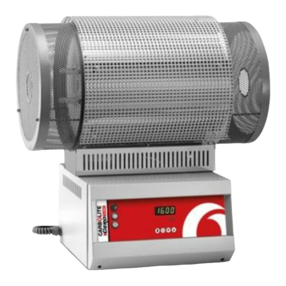
- Page 1 Installation, Operation and Maintenance Instructions 1600 °C Tube Furnace - STF Model: 180mm No Controller STF 16/180 + No Controller MEN-STF16180-05_NOCTRL 17-07-2018...
-
Page 2: Table Of Contents
Contents This manual is for guidance on the use of the Carbolite Gero product specified on the front cover. This manual should be read thoroughly before unpacking and using the furnace or oven. The model details and serial number are shown on the back of this manual. - Page 3 Recommended Spare Parts and Spare Parts Kit Power Adjustment Element Ageing 7.0 Repairs and Replacements Safety Warning - Disconnection from Power Supply Safety Warning - Refractory Fibre Insulation Temperature Controller Replacement Solid-State Relay Replacement Thermocouple Replacement Element Fitting and Replacement Fuse Replacement 8.0 Fault Analysis Furnace Does Not Heat Up...
-
Page 4: Symbols And Warnings
1.0 Symbols and Warnings 1.0 Symbols and Warnings Switches and Lights Instrument switch: when the instrument switch is operated the temperature control circuit is energised. Heat light: the adjacent light glows or flashes to indicate that power is being supplied to the elements. Heat switch: the switch disconnects power to the heating elements;... - Page 5 1.0 Symbols and Warnings Caution – Double Pole/Neutral Fusing...
-
Page 6: Installation
2.0 Installation 2.0 Installation Unpacking and Handling When unpacking or moving the product always lift it by its base or by both ends of the main body. Never lift it by its work tube or the surrounding insulation. Use two or more people to carry the product and control box. - Page 7 2.0 Installation Depending on the application of the product, it may be appropriate to position it under an extraction hood. Ensure the extraction hood is switched on during use. Ensure that the product is placed in such a way that it can be quickly switched off or disconnected from the electrical supply.
-
Page 8: Tube Fitting
2.0 Installation Tube Fitting Vertical Mode. The product (if a tube is also supplied) has a plate or clip to retain the tube in position. See fig.1. A End guard B Plate C Standard tube D Long tube E Strap F Ring clip Fig 1 - Vertical Tube Retention A Furnace body... - Page 9 2.0 Installation Expanded View of "Twin Clamp" End Seals: A Clamp B Seal plate C 'O' Ring seal D Seal sleeve E Clamp seal F End plate A Clamp B End plate Clamp seal (between Seal sleeve and Clamp D Seal sleeve Seal plate &...
-
Page 10: Heating Elements
2.0 Installation Under no circumstances should any objects be placed on top of the product. Always ensure that any vents on the top of the product are clear of any obstruction. Always ensure all cooling vents and cooling fans (if fitted) are clear of any obstruction. - Page 11 2.0 Installation Electrical Connection Details: Supply Types Supply Terminal Label Cable Colour Reversible or Live- Live - Neutral Live to either power conductor 1-phase L Brown to live (For USA 200-240V, connect L1) to the other power conductor Blue to neutral (For USA 200-240V, connect L2) to earth...
-
Page 12: Temperature Controller
3.0 Temperature Controller 3.0 Temperature Controller If this product is fitted with a temperature controller, instructions are provided separately. -
Page 13: 2132 Over-Temperature Controller Description (If Fitted)
4.0 2132 Over-Temperature 4.0 2132 Over-Temperature Controller Description (if fitted) Description Alarm Light Page Scroll D Down Display This over-temperature controller is fitted and supplied ready to use by Carbolite Gero. It is a digital instrument with a latching alarm, requiring no additional panel controls. The controller features easy setting of over-temperature setpoint and reading of current temperature by the over-temperature sensor. -
Page 14: Operation
4.0 2132 Over-Temperature 4.2.2 Operation When switched on, the controller lights up, goes through a short test routine and then displays the measured temperature or the over-temperature setpoint. The page key allows access to parameter lists within the controller. A single press of the page key displays the temperature units, normally set to °C;... -
Page 15: Audible Alarm
4.0 2132 Over-Temperature Audible Alarm If an audible alarm is supplied for use with the over-temperature controller, it is normally configured to sound on over-temperature condition and to stop sounding when the alarm is acknowledged as given in section 4.2. Note: the alarm may sound during controller start-up. -
Page 16: Operation
5.0 Operation 5.0 Operation Operating Cycle This product is fitted with an instrument switch which cuts off power to the control circuit. Connect the product to the electrical supply. Turn on the instrument switch to activate the temperature controller. The controller illuminates and goes through a short test cycle. -
Page 17: Operator Safety
5.0 Operation Operator Safety The ceramic materials used in the product manufacture become electrically conductive to some extent at high temperatures. DO NOT use any conductive tools within the product without isolating it. If a metal work tube is used, it must be earthed (grounded). Switch off the heater switch whenever loading or unloading the product. - Page 18 5.0 Operation It is recommended that a pressure relief system should be used to avoid an over pressurisation of the work tube. Please note: A product should not be heated up if any valves that have been fitted are closed to create a sealed volume. A sealed work tube should not be heated from cold due to the pressure increase caused by the trapped air or gas expanding during the heating process.
-
Page 19: Maintenance
6.0 Maintenance 6.0 Maintenance General Maintenance Preventive rather than reactive maintenance is recommended. The type and frequency depends on the product use; the following are recommended. 6.1.1 Cleaning The product's outer surface may be cleaned with a damp cloth. Do not allow water to enter the interior of the case or chamber. -
Page 20: Power Adjustment
6.0 Maintenance Power Adjustment The product's control system incorporates electronic power limiting. Power is supplied to the elements in bursts of approximately 0.33 seconds duration. This prevents overheating of the elements. The power limit is programmed into the product controller. A table of standard power limits is supplied with new products, it is given in section 10.0 Element Ageing Silicon carbide elements gradually increase in resistance with use;... -
Page 21: Repairs And Replacements
7.0 Repairs and Replacements 7.0 Repairs and Replacements Safety Warning - Disconnection from Power Supply Immediately switch the product off in the event of unforeseen circumstances (e.g. large amount of smoke). Allow the product to return to room temperature before inspection. Always ensure that the product is disconnected from the electrical supply before repair work is carried out. -
Page 22: Solid-State Relay Replacement
7.0 Repairs and Replacements Solid-State Relay Replacement Disconnect the product from the power supply and remove the appropriate cover as given above. Make a note of the wire connections to the solid state relay and disconnect them. Remove the solid state relay from the base panel or aluminium plate. Replace and reconnect the solid state relay ensuring that the bottom of it has good thermal contact with the base panel or aluminium plate. -
Page 23: Element Fitting And Replacement
7.0 Repairs and Replacements Element Fitting and Replacement Replacements: see section 6.6. If at any time the power limit has been increased, reset it to its original value (see section 10.0 at the back of this manual for the original value). New elements must not be mixed with aged elements. -
Page 24: Fuse Replacement
7.0 Repairs and Replacements Fuse Replacement Fuses are marked on the wiring diagram with type codes, e.g. F1, F2. For more information on fuses refer to section 10.0. Depending on model and voltage, the different fuse types may or may not be fitted. If any fuse has failed, it is advisable for an electrician to check the internal circuits. -
Page 25: Fault Analysis
8.0 Fault Analysis 8.0 Fault Analysis Furnace Does Not Heat Up The HEAT The heating element Check also that the SSR is working light is ON has failed correctly The controller shows a The HEAT The thermocouple has broken or has very high temperature light is OFF a wiring fault... -
Page 26: Product Overheats
8.0 Fault Analysis Product Overheats Product only heats up The controller when the instrument shows a very high The controller is faulty switch is ON temperature The thermocouple may be The controller faulty or may have been shows a low removed out of the heating temperature chamber... -
Page 27: Wiring Diagrams
9.0 Wiring Diagrams 9.0 Wiring Diagrams WA-11-30 Connections below show single phase with indirect safety switch(es). F1, F2, F3 Fuses Filter R1/1, R1/2 Relay Contactor Relay Cables Temperature Controller Blue Control Thermocouple Solid State Relay GR/Y Green + Yellow Safety Switch Grey Heat Lamp Pink... - Page 28 9.0 Wiring Diagrams WA-11-31 Connections below show single phase with safety switches and over-temperature control. F1, F2, F3 Fuses Filter R1/1, R1/2 Relay Contactor Relay Temperature Controller Cables Over-Temperature Controller Blue Over-Temperature Thermocouple Control Thermocouple GR/Y Green + Yellow Solid State Relay Grey Safety Switch Pink...
-
Page 29: Fuses And Power Settings
10.0 Fuses and Power Settings 10.0 Fuses and Power Settings 10.1 Fuses F1 - F3: Refer to the circuit diagrams. GEC Safeclip of the type shown Fitted if supply cable fitted. Internal (glass type F up to 16 A) Supply Fitted on board to some types 38 mm x 10 mm type F fitted on Fuses... -
Page 30: User Power Setting Adjustments
10.0 Fuses and Power Settings User Power Setting Adjustments Date % Power Comments Note: If a new set of elements are fitted then return the power settings to the original value. Please refer to the rating label for product specific information. -
Page 31: Specifications
11.0 Specifications 11.0 Specifications Carbolite Gero reserves the right to change the specification without notice. Work Tube Heated Work Tube Model Temp Power Length Length Weight Bore (mm) (°C) (kW) (mm) (mm) (kg) Tube furnaces heated by silicon carbide elements STF 16/180 1600 600-900... - Page 33 Notes Service Record Engineer Name Date Record of Work...
- Page 34 The products covered in this manual are only a small part of the wide range of ovens, chamber furnaces and tube furnaces manufactured by Carbolite Gero for laboratory and industrial use. For further details of our standard or custom built products please contact us at the address below, or ask your nearest stockist.
Need help?
Do you have a question about the Carbolite Gero STF 16/180 and is the answer not in the manual?
Questions and answers