
Related Manuals for VERDER Carbolite Gero HT 4/220


Summary of Contents for VERDER Carbolite Gero HT 4/220
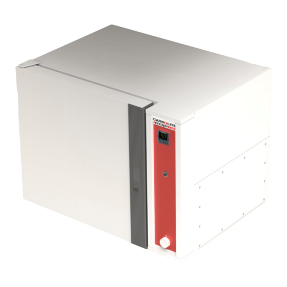
- Page 1 Installation, Operation and Maintenance Instructions 400°C High Temperature Oven - HT Model: 220 Litres No Controller HT 4/220 + No Controller MEN-HT04220-005_NOCTRL (01-09-2022)
-
Page 2: Table Of Contents
Contents This manual is for guidance on the use of the Carbolite Gero product specified on the front cover. This manual should be read thoroughly before unpacking and using the furnace or oven. The model details and serial number are shown on the back of this manual. - Page 3 Safety Warning - Refractory Fibre Insulation Control Panel Removal Temperature Controller Replacement Solid-State Relay Replacement Thermocouple Replacement Element Replacement Fuse Replacement 7.0 Fault Analysis Oven Does Not Heat Up Oven Overheats 8.0 Wiring Diagrams WV-11-00/01 WV-33-00/01 WV-43-00/01 WS-10-01 - Isolating for 208 V version only 8.5 WS-14-04 9.0 Fuses and Power Settings Fuses...
-
Page 4: Symbols And Warnings
1.0 Symbols and Warnings Switches and Lights Instrument switch: when the instrument switch is operated the temperature control circuit is energised. Solenoid valve (if fitted): see section 4.6 for full details Variable speed fan (if fitted): see section 4.7 for full details Exhaust fan (if fitted): see section 4.8 for full details Stoving and curing (if fitted): see section 4.9 for full details General Warnings... - Page 5 DANGER – Read any warning printed next to this symbol. Caution – Double Pole/Neutral Fusing...
-
Page 6: Installation
2.0 Installation Unpacking and Handling When unpacking or moving the product, always lift by its base; do not use the door or any other projecting cover or component to support the equipment when moving it. Use a fork lift or pallet truck to move the product; position the product on a level surface and use an adequate number of personnel to safely move the product into position. - Page 7 Depending on the application of the product, it may be appropriate to position it under an extraction hood. Ensure the extraction hood is switched on during use. Ensure that the product is placed in such a way that it can be quickly switched off or disconnected from the electrical supply.
-
Page 8: Flat Pack Stand (Optional)
2.3 Flat Pack Stand (optional) The flat pack stand is available in a range of sizes depending on the dimensions of the product for which it has been ordered. Subsequently, the number of fixings may vary between the different sizes of stand. 2.3.1 Parts Supplied Stand Top (x1) -
Page 9: Flat Pack Stand Assembly
2.3.2 Flat Pack Stand Assembly... -
Page 10: Electrical Connections
Electrical Connections Connection by a qualified electrician is recommended. All models covered by this manual may be ordered for single phase A.C. supply, which may be Live to Neutral non-reversible, Live to Neutral reversible or Live to Live. - Page 11 Check the product rating label before connection. The supply voltage should agree with the voltage on the label and the supply capacity should be sufficient for the current on the label. The supply should be fused at the next size equal to, or higher than the current on the label.
-
Page 12: Temperature Controller
3.0 Temperature Controller If this product is fitted with a temperature controller, instructions are provided separately. -
Page 13: Operation
4.0 Operation Operating Cycle The product is fitted with an instrument switch. The switch cuts off power to the controllers and elements. The circulation fan will operate when the instrument switch is on. An optional door switch may be fitted. If so, ensure that the door is closed to operate the fans and heating elements. -
Page 14: Atmospheres
Atmospheres When an optional gas inlet is fitted, there is a label near the inlet saying "INERT GAS ONLY". In practice, inert or oxidising gases may be used, but not combustible or toxic gases. The chamber is not gas tight, the gas usage may be high and the chamber is always likely to contain some air. -
Page 15: Variable Speed Fan (If Fitted)
Variable Speed Fan (if fitted) If fitted, the variable speed control is fitted in the air circulation fan circuit. A panel mounted rotary dial is used to control the speed. Please note that there is a minimum setting at which the fan motor starts up when the product is switched on. -
Page 16: Maintenance
5.0 Maintenance General Maintenance Preventive rather than reactive maintenance is recommended. The type and frequency depends on the product use; the following are recommended. Maintenance Schedule CUSTOMER QUALIFIED PERSONNEL DANGER! ELECTRIC SHOCK. Risk of fatal injury. Only electrically qualified personnel should attempt these maintenance procedures. Frequency Maintenance Method... - Page 17 Performance Check whether the cooling fans are Cooling Fans (if fitted) working Circulating Fan Visual check to see if it is running (if fitted) Circulating Fan Check bearings and replace if neces- (if fitted) sary Element Circuit Electrical measurement Measure the current drawn on each Power Consumption phase / circuit Shelves...
-
Page 18: Cleaning
5.2.1 Cleaning The product's outer surface may be cleaned with a damp cloth. Do not allow water to enter the interior of the case or chamber. Do not clean with organic solvents. Under no circumstances should any objects be placed on top of the product. Always ensure that any vents on the top of the product are clear of any obstruction. - Page 19 In some cases the supply voltage may be outside the range 220-240 V or the 3-phase equivalent, the power limit parameter may be set to a value other than 100%. Do not increase the value to 100%, see section 9.0 for details of power limit settings.
-
Page 20: Repairs And Replacements
6.0 Repairs and Replacements Safety Warning - Disconnection from Power Supply Immediately switch the product off in the event of unforeseen circumstances (e.g. large amount of smoke). Allow the product to return to room temperature before inspection. Always ensure that the product is disconnected from the electrical supply before repair work is carried out. -
Page 21: Temperature Controller Replacement
Control panel - HT models. Remove the screws holding the panel. Note that the panel remains connected by wiring. Do not disconnect any wiring without first making a careful note of all the connections. Internal element cover. Open the door, remove any screws holding the panel and any clips holding thermocouples in position and remove the cover. -
Page 22: Element Replacement
Element Replacement Remove the back panel and the internal cover as given above. The element terminals are accessed from the back. Disconnect the wires from the heating element terminals. Remove any starlock washers - these may need to be cut with wire cutters. Remove any clips holding the element inside the chamber and withdraw the ele- ment. -
Page 23: Fault Analysis
7.0 Fault Analysis Oven Does Not Heat Up temperature No power from Check the fuses in the supply controller is supply line The controller shows a very high temperature The temperature sensor has temperature or a controller is broken or has a wiring fault code such as EEE or --- or S.br The SSR could be failing to... -
Page 24: Wiring Diagrams
8.0 Wiring Diagrams WV-11-00/01 Connections below show single phase with indirect safety switches, fan motor (if fitted) and over-temperature control. - Page 25 WV-33-00/01 Connections below show 3-phase +N with indirect safety switches, fan motor (if fitted) and over-temperature control. WV-43-00/01 Connections below show 3-phase Delta with indirect safety switches, fan motor (if fitted) and over-temperature control (if fitted).
-
Page 26: Ws-10-01 - Isolating For 208 V Version Only
WS-10-01 - Isolating for 208 V version only The transformer changes the supply voltage of the control circuit into the desired operating range for the controller and other components. The supply voltage as shown is taken from a single phase supply or from the phase-to- phase voltage of a 3-phase supply. -
Page 27: Ws-14-04
8.5 WS-14-04 The supplementary wiring diagram below shows the connections for a door switch on a fan oven with an existing contactor but no spare contact. The door switch is included in the contactor coil circuit. If there is no spare contact available, an additional relay is required. Circulation Fan Coil Door Switch... -
Page 28: Fuses And Power Settings
9.0 Fuses and Power Settings Fuses F1-F2: Refer to the circuit diagrams. Fitted if supply cable fitted. Internal 38 mm x 10 mm type F fitted on Supply Fitted on board to some types EMC filter circuit board(s) Fuses of EMC filter. Fitted on board to some types 2 Amps glass type F of EMC filter. -
Page 29: Specifications
10.0 Specifications Carbolite Gero reserves the right to change the specification without notice. Approx Chamber Size (mm) Max Temp Max Power Capacity Model Weight (°C) (kW) (kg) Industrial High Temperature Ovens HT 4/220 10.1 Environment The models listed in this manual contain electrical parts and should be stored and used in indoor conditions as follows: Temperature: 5 °C - 40 °C... - Page 31 Notes Service Record Engineer Name Date Record of Work...
- Page 32 The products covered in this manual are only a small part of the wide range of ovens, chamber furnaces and tube furnaces manufactured by Carbolite Gero for laboratory and industrial use. For further details of our standard or custom built products please contact us at the address below, or ask your nearest stockist.
Need help?
Do you have a question about the Carbolite Gero HT 4/220 and is the answer not in the manual?
Questions and answers