
Related Manuals for VERDER Carbolite Gero PN 30


Summary of Contents for VERDER Carbolite Gero PN 30
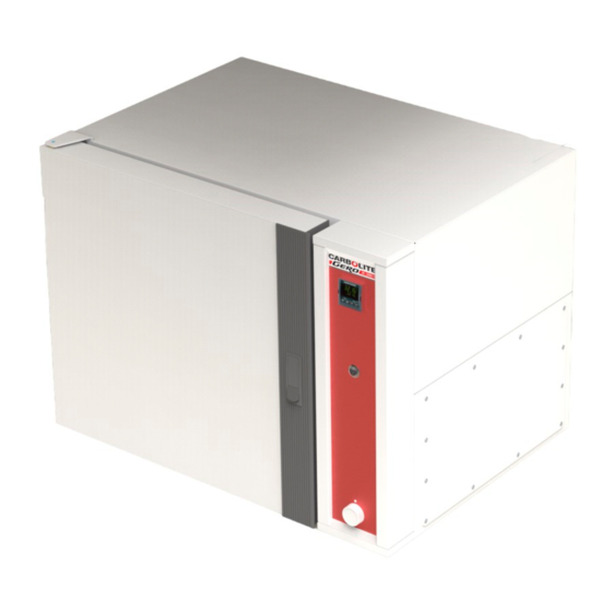
- Page 1 Installation, Operation and Maintenance Instructions 300 °C Peak Natural Convection Oven - PN Model: 30 Litres No Controller PN 30 + No Controller MEN-PN030-006_NOCTRL (05-01-2023)
-
Page 2: Table Of Contents
Contents This manual is for guidance on the use of the Carbolite Gero product specified on the front cover. This manual should be read thoroughly before unpacking and using the furnace or oven. The model details and serial number are shown on the back of this manual. - Page 3 6.0 Repairs and Replacements Safety Warning - Disconnection from Power Supply Safety Warning - Refractory Fibre Insulation 6.3 Panel Removal Temperature Controller Replacement Solid-State Relay Replacement Thermocouple Replacement Element Replacement Fuse Replacement 7.0 Fault Analysis Oven Does Not Heat Up Oven Overheats 8.0 Wiring Diagrams WV-11-00...
-
Page 4: Symbols And Warnings
1.0 Symbols and Warnings Switches and Lights Instrument switch: when the instrument switch is operated the temperature control circuit is energised. Door lock indicator: When this lamp is illuminated, the door is locked and cannot be opened. Interior light: when the interior light switch is operated the interior light illuminates. - Page 5 DANGER – Read any warning printed next to this symbol. Caution – Double Pole/Neutral Fusing...
-
Page 6: Installation
2.0 Installation Unpacking and Handling Remove the shelves and runners from the packaging before attempting to move the equipment. When unpacking and handling the product, always lift it by its base. Do not use the door or any other projecting cover or component to support the equipment when moving it. - Page 7 Ensure that the product is placed in such a way that it can be quickly switched off or disconnected from the electrical supply. Under no circumstances should any objects be placed on top of the product. Always ensure that any vents on the top of the product are clear of any obstruction.
-
Page 8: Shelf Fitting
2.2.1 Shelf Fitting Runner Shelf To fit the shelves: 1. Insert the runner into the slots in the side of the oven chamber, as shown in fig- ures 1 and 2 2. Rotate the runner downwards by 90° so that the runner hooks into place and cre- ates a level surface upon which the shelf can securely rest, as shown in figures 3 and 4 3. - Page 9 Figure 3: Figure 4: Rotating runner into position Runner in position Figure 5: Figure 6: Shelf resting on runners with spur at rear of chamber Shelves fitted (highlighted in green)
-
Page 10: Flat Pack Stand (Optional)
2.3 Flat Pack Stand (optional) The flat pack stand is available in a range of sizes depending on the dimensions of the product for which it has been ordered. Subsequently, the number of fixings may vary between the different sizes of stand. 2.3.1 Parts Supplied Stand Top (x1) -
Page 11: Flat Pack Stand Assembly
2.3.2 Flat Pack Stand Assembly... -
Page 12: Electrical Connections
Electrical Connections Connection by a qualified electrician is recommended. All models covered by this manual may be ordered for single phase A.C. supply, which may be Live to Neutral non-reversible, Live to Neutral reversible or Live to Live. - Page 13 Check the product rating label before connection. The supply voltage should agree with the voltage on the label and the supply capacity should be sufficient for the current on the label. The supply should be fused at the next size equal to, or higher than the current on the label.
-
Page 14: Temperature Controller
3.0 Temperature Controller If this product is fitted with a temperature controller, instructions are provided separately. -
Page 15: Operation
4.0 Operation Operating Cycle This product is fitted with an instrument switch which cuts off power to the control circuit. Connect the product to the electrical supply. Turn on the instrument switch to activate the temperature controllers. The controllers illuminate and go through a short test cycle. Over-Temperature option only. -
Page 16: Temperature Uniformity
Temperature Uniformity Where accurate temperature control of the load is important, use the central part of the chamber and place or distribute the load to allow free air circulation. Do not place loads on the chamber floor: use the bottom shelf. Explosive Vapours Unless your product includes the stoving and curing option, this model is not suitable for drying or heat treatment applications where... -
Page 17: Stoving And Curing (If Fitted)
Start the extraction process using the switch on the control panel; this is only functional when the instrument switch is on. When the unit is turned on, there may be a drop in internal temperature until the product recovers to the setpoint value. The amount of air exhaust can be controlled by adjusting the vent control knob on the control panel. - Page 18 When the exhaust fan is turned on, there may be a drop in internal temperature before the product recovers to the setpoint value. The airflow should be adjusted to the minimum required by the process to reduce the amount of energy wasted in heating air.
-
Page 19: Maintenance
5.0 Maintenance General Maintenance Preventive rather than reactive maintenance is recommended. The type and frequency depends on the product use; the following are recommended. Maintenance Schedule CUSTOMER QUALIFIED PERSONNEL DANGER! ELECTRIC SHOCK. Risk of fatal injury. Only electrically qualified personnel should attempt these maintenance procedures. Frequency Maintenance Method... - Page 20 Performance Check whether the cooling fans are Cooling Fans (if fitted) working Circulating Fan Visual check to see if it is running (if fitted) Circulating Fan Check bearings and replace if neces- (if fitted) sary Element Circuit Electrical measurement Measure the current drawn on each Power Consumption phase / circuit Shelves...
-
Page 21: Cleaning
5.2.1 Cleaning The product's outer surface may be cleaned with a damp cloth. Do not allow water to enter the interior of the case or chamber. Do not clean with organic solvents. Under no circumstances should any objects be placed on top of the product. - Page 22 In some cases the supply voltage may be outside the range 220-240 V or the 3-phase equivalent, the power limit parameter may be set to a value other than 100%. Do not increase the value to 100%, see section 9.0 for details of power limit settings.
-
Page 23: Repairs And Replacements
6.0 Repairs and Replacements Safety Warning - Disconnection from Power Supply Immediately switch the product off in the event of unforeseen circumstances (e.g. large amount of smoke). Allow the product to return to room temperature before inspection. Always ensure that the product is disconnected from the electrical supply before repair work is carried out. -
Page 24: Panel Removal
6.3 Panel Removal Disconnect the product from the electrical supply. Control panel: Open the door and remove two screws located in recesses on the left side of the control panel (these screws are covered with plastic caps). Lift the panel, pull forward the bottom of the panel and lower the panel to disengage it from the top of the body. -
Page 25: Element Replacement
1. Disconnect the thermocouple to be replaced from its terminal block and withdraw 2. Re-assemble the new thermocouple, observing the colour coding. 3. Refit the element access panel. Element Replacement Remove the control panel and the internal element cover (see section 6.3). The ele- ment terminals are located in the side compartment. -
Page 26: Fault Analysis
7.0 Fault Analysis Oven Does Not Heat Up temperature No power from Check the fuses in the supply controller is supply line The controller shows a very high temperature The temperature sensor has temperature or a controller is broken or has a wiring fault code such as EEE or --- or S.br The SSR could be failing to... -
Page 27: Wiring Diagrams
8.0 Wiring Diagrams WV-11-00 Connections below show single phase with instrument switch(es). F1, F2 Fuses Filter Instrument Switch Temperature Con- troller Thermocouple Solid State Relay Element(s) If Fitted Live Neutral Earth (GR/Y) (Green+Yellow) - Page 28 WV-11-01 F1, F2 Fuses Filter Instrument Switch Relay (Coil) R1/1, R1/2 Relay Contactor Temperature Controller Over-Temperature Controller Thermocouple Solid State Relay Element(s) If Fitted Live Neutral Earth PE (GR/Y) (Green+Yellow)
- Page 29 WV-11-04 Connections below show single phase with hydraulic thermostat. F1, F2 Fuses Filter Instrument Switch Temperature Controller Thermocouple Hydraulic Thermostat Fault Light Solid State Relay Element(s) If Fitted Live Neutral Earth (GR/Y) (Green+Yellow) Note on Hydraulic Thermostat: When used over 16 Amps or in a 2- or 3-phase model, the product is fitted with a contactor;...
-
Page 30: Fuses And Power Settings
9.0 Fuses and Power Settings Fuses F1-F2: Refer to the circuit diagrams. Fitted if supply cable fitted. Internal 38 mm x 10 mm type F fitted on Supply Fitted on board to some types EMC filter circuit board(s) Fuses of EMC filter. Fitted on board to some types 2 Amps glass type F of EMC filter. -
Page 31: Specifications
10.0 Specifications Carbolite Gero reserves the right to change the specification without notice. Chamber Size Max Power Approx (mm) Model Temp Weight (kW) Capacity (l) (°C) (kg) Peak Range Ovens - no fans PN 30 0.75 10.1 Environment The models listed in this manual contain electrical parts and should be stored and used in indoor conditions as follows: Temperature: 5 °C - 40 °C... - Page 33 Notes Service Record Engineer Name Date Record of Work...
- Page 34 The products covered in this manual are only a small part of the wide range of ovens, chamber furnaces and tube furnaces manufactured by Carbolite Gero for laboratory and industrial use. For further details of our standard or custom built products please contact us at the address below, or ask your nearest stockist.
Need help?
Do you have a question about the Carbolite Gero PN 30 and is the answer not in the manual?
Questions and answers