Table of Contents
Advertisement
Advertisement
Table of Contents

Related Manuals for CEMB SM825


Summary of Contents for CEMB SM825
- Page 1 SM825 ver.T Semi-Automatic Car Tire Changer Manual 1 / 28 REV. 01...
- Page 2 PRINTING CHARACTERS AND SYMBOLS Throughout this manual, the following symbols and printing characters are used to facilitate reading: Indicates the operations which need proper care Indicates prohibition Indicates a possibility of danger for the operators BOLD TYPE Important information WARNING: before operating the lift and carrying out any adjustment, read carefully chapter 7 “installation”...
-
Page 3: Table Of Contents
CONTENTS INTRODUCTION GENERAL INFORMATION TRANSPORT, UNPACKING AND STORAGE INSTALLATION OPERATION INFLATING MAINTENANCE TROUBLESHOOTING ELECTRIC AND PNEUMATIC DIAGRAM 3 / 28 REV. 01... -
Page 4: Introduction
CHAPTER 1 – INTRODUCTION INTRODUCTION Thank you for purchasing a product from the line of tire changers. The machine has been manufactured in accordance with the very best quality principles. Follow the simple instructions provided in this manual to ensure the correct operation and long life of the machine. Read the entire manual thoroughly and make sure you understand it. - Page 5 Any tampering or modification to the equipment carried out without the manufacturer’s prior • authorization will free him from all responsibility for damage caused directly or indirectly by the above actions. Removing or tampering with safety devices immediately invalidates the guarantee. •...
-
Page 6: General Information
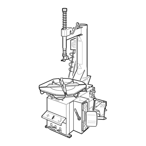
CHAPTER 2 – GENERAL INFORMATION INTENDED USE • This Semi-automatic tire changer has been designed and manufactured exclusively for removing and mounting tires from/onto rims from 10" to 26" and a maximum diameter of 1000 mm. • In particular THE MANUFACTURER cannot be held responsible for any damage caused through the use of this tire changer for purposes other than those specified in this manual, and therefore inappropriate, incorrect and unreasonable. - Page 7 DANGER WARNING SIGNS 7 / 28 REV. 01...
- Page 8 TECHNICAL SPECIFICATION 12" - 26" External locking rim dimension 13" - 27" 14" - 28" 14" – 28” Internal locking rim dimension 15" - 29" 16" - 30" Max. tire diameter 1200mm (47.5”) Max tire width 470mm (18.5”) Force on bead breaker blade (10 bar) 2500 kg Working pressure 8 bar (116 psi)
-
Page 9: Transport, Unpacking And Storage
CHAPTER 3 – TRANSPORTATION, UNPACKING AND STORAGE TRANSPORTATION The tire changer must be transported in its original packaging and kept in the position shown • on the package itself. • The packaged machine may be moved by means of a fork lift truck of suitable capacity. Insert the forks at the points shown in figure 3. -
Page 10: Installation
CHAPTER 4 – INSTALLATION 4.1 SPACE REQUIRED When choosing the place of installation be sure that it complies with current safety at work regulations. The tire changer must be connected to the main electric power supply and the compressed air •... - Page 11 POSITIONING AND PARTS ASSEMBLY Unscrew the pallet fixing screws and set the tire changer on the floor. • Unscrew the 4 screws from the body, set the vertical arm into the proper seat and fix the screw • again (Fig. 5/a). Make sure the horizontal arm is on the vertical arm’s support and the pin is locked with nuts •...
- Page 12 12 / 28 REV. 01...
- Page 13 4.2.2 Mounting and connecting the GT • Route the tube (1), situated inside the machine body, though the hole on the back side of the body. • Connect the hose (4) to the connectors (2) using the bands (3). 4.2.3 Mounting and connecting the manometer •...
- Page 14 COMMISSIONING Any electric connection job must be carried out by professionally qualified personnel. Make sure that the power supply is right. Make sure the connection of the phases is right. Improper electrical hook-up can damage motor and will not be covered under warranty. Check to make sure the characteristics of your systems correspond to those required by the •...
- Page 15 4.4.1 GT version Do NOT LEAN on the turntable during this operation. Possibly dirty dust on turntable could offend the operator’s eyes. For the same reason, be carefully as not to accidentally push the inflating pedal while working. When the pedal located on the left side of the machine •...
-
Page 16: Operation
CHAPTER 5 – OPERATION Do not use the machine until you have read and understood the entire manual and the warning provided. Before carrying out any operation, deflate the tire and take off all the wheel balancing weights. The operation of the tire changer is divided into three parts: a) BREAKING THE BEAD b) REMOVING THE TIRE c) MOUNTING THE TIRE... - Page 17 REMOVING THE TIRE Before any operation make sure to remove the old wheel balancing weights and check that the tire is deflated. During arm tilting make sure that nobody stats behind the tire changer. Spread the supplied grease (or grease of a similar type) onto the tire bead. •...
- Page 18 Chains, bracelets, loose clothing or foreign objects in the vicinity of the moving parts can represent a danger for the operator. MOUNTING THE TIRE It is utmost important to check the tire and rim to prevent tire explosion during the inflating operations. Before beginning mounting operation, make sure that: The tire and cord fabric are not damaged.
- Page 19 Never keep your hands onto the wheel: the arm recovery to “working position” could set the operator at risk of hand crushing between rim and mounting head. Move the tire so that the bead passes below the front section of the mounting head and is •...
-
Page 20: Inflating
CHAPTER 6 – INFLATING The greatest attention is called for when inflating the tires. Keep strictly to the following instructions since the tire changer is NOT designed and built to protect (or anyone else in the vicinity of the machine) if the tire bursts accidentally. - Page 21 INFLATING TIRES WITH GT SYSTEM The GT inflating system facilitates inflation of tubeless tires to a powerful jet of air from the nozzle positioned on the clamps. During this phase of work he level of noise can reach 85db (A). It is advisable to use a noise protection.
-
Page 22: Maintenance
CHAPTER 7 – MAINTENANCE 7.1 GENERAL WARNINGS Unauthorized personnel may not carry out maintenance work. • Regular maintenance as described in the manual is essential for correct operation and long lifetime of the tire changer. • If maintenance is not carried out regularly, the operation and reliability of the machine may be compromised, thus placing the operator and anyone else in the vicinity at risk. - Page 23 If necessary to adjust the vertical arm locking plate because the tool does not lock or it does not rise from the rim of 2mm necessary for working, adjust nuts as shown in Fig. 17. For cleaning or replacing the silencer for opening/closing clamps, see Fig 18 and proceed as follows: 1.
-
Page 24: Troubleshooting
CHAPTER 8 – TROUBLE-SHOOTING ROUBLE OSSIBLE AUSE OLUTION Turntable rotates only in Reverser broken Replace reverser one direction. Belt broken Replace Reverser broken Replace reverser Turntable does not rotate. Check for loose wire in the motor, plug or socket. Problem with motor Replace motor Adjust the belt tension (chap. -
Page 25: Electric And Pneumatic Diagram
CHAPTER 9 – ELECTRIC AND PNEUAMTIC DIAGRAM 110V/220V/230V – 1PH 220V/230V/380V/400V – 3PH (SINGLE SPEED) 25 / 28 REV. 01... - Page 26 220V/230V/380V/400V – 3PH (DOUBLE SPEED) 26 / 28 REV. 01...
- Page 27 STANDARD PNEUMATIC SYSTEM DIAGRAM Inflating gauge Turntable valve Silencer 1/4” Rotation union Silencer 1/8” Lubricator Quick relief valve Pressure regulator Bead breaker cylinder Air intake cock Turntable cylinder Safety valve Bead breaking valve Pressure regulator 27 / 28 REV. 01...
- Page 28 GT PNEUMATIC SYSTEM DIAGRAM Safety Valve Divider Tank Pressure gauge Setting solenoid valve Inflating unit GT pedal valve Deflating valve Safety Valve Rotation union Inflating head 28 / 28 REV. 01...
Need help?
Do you have a question about the SM825 and is the answer not in the manual?
Questions and answers