
Summary of Contents for RAVEO RM72A
- Page 1 User Manual RM72A 2-Phase Digital Stepper Drive Hardware Version 2.0 Manual Revision 1.0...
-
Page 2: Table Of Contents
RM72A Digital Stepper Drive User Manual Table of Contents 1. Introductions ..........................................1 1.1 Features ............................................1 1.2 Applications ..........................................1 2. Specifications ..........................................1 2.1 Electrical Specifications ........................................ 1 2.2 Environment ..........................................2 2.3 Mechanical Specifications ......................................2 2.4 Elimination of Heat ........................................2 3. -
Page 3: Introductions
1.2 Applications The RM72A stepper drive are designed to power 2 phase (1.8°) or 4-phase (0.9°) NEMA 23, 24, 34, and 42 hybrid stepper motors. It can be easily adopted in many industries (CNC, medical, automation, packaging…), such as X-Y tables, engraving machines, labeling machines, mills, plasma, laser cutters, pick and place devices, and so on. -
Page 4: Environment
Side mounting recommended for better heat dissipation 2.4 Elimination of Heat RM72A reliable working temperature should be < 60℃ (140°F) It is recommended to use automatic idle-current mode to reduce motor heating. That means set the SW4 pin of DIP switch at “OFF” position. -
Page 5: Connection Pin Assignments And Led Indication
Connectors, DIP switches, and LED locations The RM72A has three connector blocks P1&P2&P3 (see above picture). P1 is for control signals connections, and P2 is for output signals connections, P3 is for power and motor connections. The following tables are brief descriptions of the three connectors. -
Page 6: P3 - Motor And Power Supply Connector
3.4 P4 - Tuning Connector RM72A has a tuning port with RS232 to modify the drive parameters, it is just used to modify parameter, not for equipment control because neither precision nor stability is sufficient. If you need a field bus drive, use a RS485 or... -
Page 7: Control Signal And Output Signal
Fault Output When over voltage or over current protection happens, RM72A red status LED light will blink and the impedance state between ALM+ and ALM- will change (from low to high or high to low depending on configuration) and can thus be detected. -
Page 8: Motor Connection
Brake output 5. Motor Connection The RM72A can drive 2-phase and 4-pahse bipolar hybrid stepper motors with 4, 6, or 8 wires. 5.1 Connections of 4-lead Motor The 4 lead motors are the least flexible and easy to connect. And the Speed – torque of motor depends on winding inductance. -
Page 9: Full Coil Configuration
RM72A Digital Stepper Drive User Manual Figure 10: 6-lead motor half coil (higher speed) connections 5.2.2 Full Coil Configuration The full coil configuration on a six lead motor should be used in applications where higher torque at lower speed is desired. -
Page 10: Power Supply Selection
6. Power Supply Selection The RM72A can power medium and large size stepping motors (frame size from NEMA 23 to 42). To get good driving performances, it is important to select supply voltage and output current properly. Generally speaking, supply voltage determines the high speed performance of the motor, while output current determines the output torque of the driven motor (particularly at lower speed). -
Page 11: Dip Switch Configurations
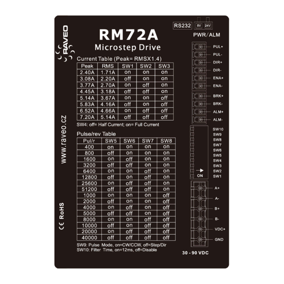
7. DIP Switch Configurations The RM72A has one 10-bit DIP switch and one 1-bit selector. The first 10-bit is used to configure settings of micro step resolution, output current, motor standstill current, pulse type and smoothing time as shown below. -
Page 12: Dynamic Current Configurations
12ms acceleration time. 7.3 Automatic Motor Matching & Self Configuration When powered on a RM72A will automatically configure itself with the best settings to match the driven stepper motor for optimal performance. No action is needed. 8. Wiring Notes In order to improve anti-interference performance of the drive, it is recommended to use twisted pair shield cable. -
Page 13: Typical Connection
RM72A Digital Stepper Drive User Manual 9. Typical Connection A complete stepping system should include stepping motor, stepping drive, power supply and controller (pulse generator). A typical connection is shown as below. Controller Drive PUL+ Step PUL- DIR+ Direction DIR-... -
Page 14: Protection Functions
RM72A Digital Stepper Drive User Manual 11. Protection Functions To improve reliability, the drive incorporates some built-in protections features. Time(s) of Priority Sequence wave of red LED Description Blink Over-current protection activated when peak current exceeds the limit. Over-voltage protection activated when drive working voltage is greater than 160VDC Reserved. -
Page 15: Troubleshooting
RM72A Digital Stepper Drive User Manual 12. Troubleshooting In the event that your drive doesn’t operate properly, the first step is to identify whether the problem is electrical or mechanical in nature. The next step is to isolate the system component that is causing the problem. As part of this process you may have to disconnect the individual components that make up your system and verify that they operate independently. -
Page 16: Warranty
RM72A Digital Stepper Drive User Manual 13. Warranty Twelve Month Warranty Exclusions The above warranty does not extend to any product damaged by reasons of improper or inadequate handlings by customer, improper or inadequate customer wirings, unauthorized modification or misuse, or operation beyond the electrical specifications of the product and/or operation beyond environmental specifications for the product.
Need help?
Do you have a question about the RM72A and is the answer not in the manual?
Questions and answers